
Light-Wave Voice-Communication Receiver Circuit
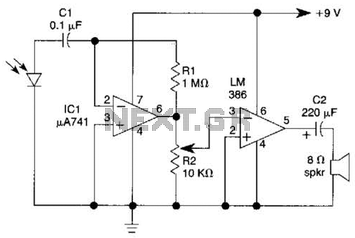
This light-wave receiver circuit is designed to efficiently detect and amplify light signals. The core components include the 741 operational amplifier, which acts as a preamplifier to boost the weak signals received from the light detectors. The LM386 then serves as a power amplifier, increasing the signal strength further for transmission or processing.
The gain control potentiometer, R2, allows for fine-tuning of the amplification level, enabling the user to adapt the circuit's sensitivity based on the specific requirements of the application. This feature is particularly important when dealing with varying light conditions or when using different types of light detectors.
Phototransistors are a popular choice for light detection due to their high sensitivity; however, they are not ideal in high ambient light conditions. In such environments, the use of a 100 kΩ series resistor is recommended to limit current and protect the phototransistor from potential damage. The circuit can also accommodate other types of light detectors, such as solar cells, photodiodes, and LEDs. These alternatives can provide reliable performance, especially when matched with the semiconductor material of the light source, ensuring compatibility and optimal operation.
Overall, this light-wave receiver circuit is versatile and adaptable, making it suitable for various applications, including remote control systems, light-based communication, and environmental monitoring. Proper selection of components and careful consideration of gain settings will enhance the circuit's effectiveness in diverse operational conditions. This light-wave receiver consists of a 741 operated as a preamplifier and an LM386 operated as a power amplifier. Potentiometer R2 is the gain control. Various kinds of detectors can be used as the front end of the receiver. Phototransistors are very sensitive, but they do not work well in the presence of too much ambient light.
A 100-kQ series resistor is required if you use a phototransis-tor. Solar cells, photodiodes, and LEDs of the same semiconductor as the transmitter all work well in this circuit. 🔗 External reference
Related Circuits
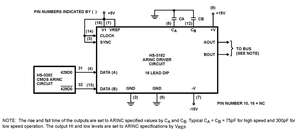
The HS-3182 is a monolithic dielectrically isolated bipolar differential line driver designed to meet the specifications of ARINC 429. This device is intended to be used with a companion chip, the HS-3282 CMOS ARINC Bus Interface Circuit, which provides...
A circuit is required where, upon power application, a timer triggers, keeping a relay in the off state. Once the timer completes its cycle, the relay will activate. The circuit design consists of a timer integrated with a relay to...
A circuit has been identified that integrates a voltage regulator and filter to isolate the voltage supplied by the receiver for powering an operational amplifier (op-amp) that drives a meter. Additionally, the circuit isolates the carrier frequency from the...
If the reader arrived here via Google, they may have encountered other circuits for high-power LED driving that include many components such as inductors, operational amplifiers, various regulator ICs, transistor feedback networks, and microcontrollers. While those circuits tend to...
The circuit depicted is designed to protect a system from power supplies that may exceed safe limits. An example of this is small consumer products that utilize external AC adapters, where there is a risk of accidentally connecting the...
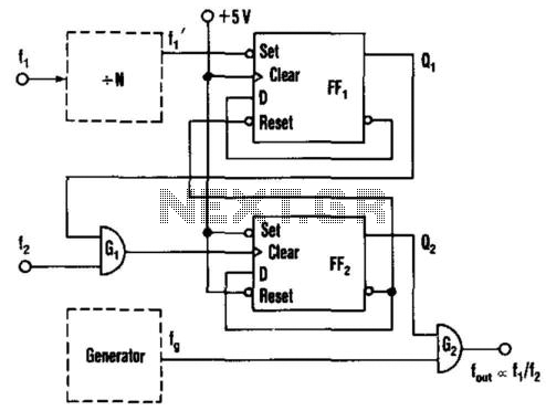
This circuit generates an output frequency that is linearly proportional to the ratio of two input frequencies. Each pulse of the bias frequency will open a switch for a period equal to half of the second input frequency, allowing...
Warning: include(partials/cookie-banner.php): Failed to open stream: Permission denied in /var/www/html/nextgr/view-circuit.php on line 713
Warning: include(): Failed opening 'partials/cookie-banner.php' for inclusion (include_path='.:/usr/share/php') in /var/www/html/nextgr/view-circuit.php on line 713