
DIY Satellite Finder Circuit
The described circuit functions primarily as a signal processing unit for satellite communications. The voltage regulator ensures that the op-amp receives a stable voltage supply, which is crucial for accurate signal amplification. The filtering stage is designed to eliminate any noise from the power supply, providing clean voltage to the op-amp, thereby enhancing the performance of the entire circuit.
The isolation of the carrier frequency is pivotal for the circuit's operation, as it allows for the extraction of relevant signals from the satellite transmission. The rectification process converts the alternating current (AC) signal into direct current (DC), which is necessary for the subsequent amplification stage. The amplifier's output is directly linked to the meter, which provides a visual representation of the signal strength or quality, enabling users to assess satellite reception.
In terms of component selection, while the meter represents the most significant expense, the overall design favors a cost-effective approach by utilizing readily available electronic components. The intention to employ a volt-ohm meter in the DIY version suggests a focus on versatility and customization, allowing users to adapt the circuit to their specific needs with minimal investment.
The satellite look angle calculator represents an additional tool for users involved in satellite installations. By calculating the necessary angles for optimal satellite alignment, it simplifies the installation process and enhances the effectiveness of satellite reception. The incorporation of magnetic declination data further increases the accuracy of site surveys, making it a valuable resource for technicians and hobbyists alike. Future developments for mobile platforms indicate a commitment to expanding accessibility and functionality, catering to a broader audience of satellite users.Ok, I have been looking for this circuit on line now for a while and I finally found it. (Thank you Kostas 711 in Patras City, Greece. ) Turns out it is a pretty simple circuit. Part of it is a voltage regulator and filter to isolate the voltage supplied by the receiver and using it to power an op-amp which will run the meter. The rest of it isolat es the carrier frequency from the satellite, rectifies it, and feeds it to the amp input. The amp output drives the meter. Voila! Now I know why these things are so cheap. The most expensive component is the meter. I saw some other DIYers looking for this online as well so here it is just in case they Google me. I still would like to try to build it myself and use my volt-ohm meter for the display, perhaps without the op-amp. Maybe just a couple of caps, rectifiers, and a choke, Use a couple of RCA jacks for the output to the meter.
Voila! I`ve also created my own satellite look angle calculator for Windows. I found the formulas for the elevation, azimuth and skew by looking through some learning material on the subject. They didn`t have the development of the formulas but they had some sample problems. I also found some data regarding magnetic declinations to add in, since I use a compass to do my site surveys.
Right now the calculator only does the North American continent and DirecTV and Dish satellites. I am working on an upgrade and would also like to develop it for my Palm phone. The iPhone and Touch would be fun to do too, but I do not have a Mac for development. Perhaps later. 🔗 External reference
Related Circuits
The generator consists of an integrator functioning as a ramp generator and a threshold detector with hysteresis acting as a reset circuit. The integrator has been previously described and does not require further elaboration. The threshold detector operates similarly...
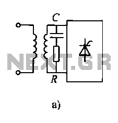
Diodes and thyristors have limited tolerance to over-current and over-voltage conditions. Short-term exposure to excessive voltage or current can damage these components and prevent them from achieving their full potential. The parameters of these devices should be determined based...
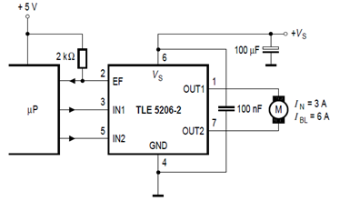
The schematic below illustrates the TLE5206-2 5A H-Bridge circuit for DC motor applications. This device features an integrated power H-bridge with DMOS output stages designed specifically for driving DC motors, as indicated in the datasheet. The TLE5206-2 circuit application...
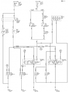
The connection and wiring between each part and component of the exterior lighting system of the vehicle includes elements such as the fusible link, junction block, tail light relay, cruise control, stop light switch, relay box, column switch, rear...
This circuit is a small +5V power supply, which is useful when experimenting with digital electronics. Small inexpensive wall transformers with variable output voltage are available from any electronics shop and supermarket. Those transformers are easily available, but usually...
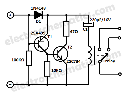
This low current relay circuit is designed for use in battery-operated electronic devices. Its operating current is in microamperes (µA). This is achieved by using a bistable relay and incorporating additional components to enable the relay to function like...