
5v Regulated Solar Power Supply Circuit
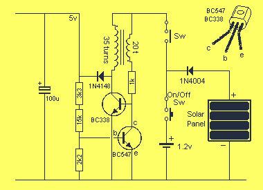
The project utilizes a 1.2V rechargeable battery and a solar panel sourced from inexpensive solar garden lights, effectively integrating these components into a compact and cost-effective power supply solution. The overall design aims to provide a regulated 5V output capable of delivering 10mA, suitable for powering microcontrollers and other low-power electronic devices.
The circuit architecture includes an oscillator transistor and a regulator transistor. The oscillator is critical for generating the high-voltage pulses necessary for the operation of the transformer, which is configured for positive feedback. This feedback mechanism ensures that when the oscillator transistor is triggered, it saturates the transformer core, producing a substantial magnetic flux that induces a voltage in the secondary winding. The output is then rectified and smoothed by an electrolytic capacitor to deliver a stable 5V supply.
A diode is strategically placed between the solar panel and the battery to prevent reverse current flow, which could drain the battery when sunlight is insufficient. The regulator transistor plays a crucial role in maintaining the output voltage at 5V. It monitors the voltage at a specific point in the circuit, ensuring that any load-induced voltage drop is compensated by allowing the oscillator to operate more aggressively, thereby replenishing the electrolytic capacitor.
The circuit operates at approximately 50kHz, and the use of a trimmer resistor allows for fine-tuning of the output voltage to accommodate the varying tolerance levels of different microcontrollers. Careful attention is given to the current draw; for every mA of output, approximately 5mA is drawn from the battery, necessitating the use of a high-current-rated transistor for the oscillator to ensure reliable operation.
This design exemplifies an efficient use of available components, leveraging the low cost of solar technology to create a functional power source for microcontroller applications, while also accommodating other electronic circuits such as amplifiers and FM transmitters. The consideration of quiescent current and output limits ensures the circuit remains practical for low-power applications, particularly in scenarios where power conservation is essential, such as in data logging systems that utilize sleep modes to minimize energy consumption.This project uses the 1.2v rechargeable battery and solar panel from a Solar Garden Light. These lights can be bought for less than $5.00 in most $2.00 shops or similar shops that sell general household items. We are also using the housing for this project as we could not buy the case, battery and panel for $5.00 in an electronics shop.
It is incredible that a solar panel, rechargeable battery and plastic housing can be bought for less than $5.00! We have already described the operation of the Solar Circuit, but unfortunately it cannot be used to generate a voltage higher than about 4v, so a new design had to be created.
The circuit we have designed is shown above and provides a regulated 5v output @ 10mA. If a higher current is drawn, the output voltage will drop. At 15mA, the output voltage drops to 4v. This supply has been specially designed for a microcontroller project, but it will also work for circuits such as amplifiers, FM transmitters etc. The circuit consists of an oscillator transistor and a regulator transistor. The solar panel charges the battery when sunlight is bright enough to produce a voltage above 1.9v. A diode is required between the panel and the battery as it leaks about 1mA from the battery when it is not illuminated.
The regulator transistor is designed to limit the output voltage to 5v. This voltage will be maintained over the capability of the circuit, which is about 10mA. The oscillator transistor must be a high-current type as is is turned on for a very short period of time to saturate the core of the transformer. This energy is then released as a high-voltage pulse. These pulses are then passed to the electrolytic and appear as a 5v supply with a capability of about 10mA.
If the current is increased to 15mA, the voltage drops to about 4v. The transformer is wired so that it gives POSITIVE feedback. The transistor turns on via the 1k resistor and this produces expanding flux in the core. The flux cuts the turns of the secondary winding and produces a voltage that ADDS to the turn on voltage and the transistor is turned on MORE. The transistor gets fully turned ON and the current through the primary becomes a maximum. The core becomes saturated and although the flux is a maximum, it is not expanding flux and thus the secondary produces no voltage (only the voltage and current supplied by the battery).
The voltage and current into the base of the transistor is reduced and this reduces the current through the primary. The flux now begins to collapse and this produces a voltage in the secondary of an opposite polarity.
This turns the transistor OFF and the magnetic flux collapses quickly and produces a high voltage. This voltage is passed through the diode and charges the electrolytic. The circuit operates at approx 50kHz and the pulses quickly charge the electrolytic. The 15k resistor has a 3k3 "trimmer" resistor to enable you to adjust the output to exactly 5v or slightly above 5v. Microcontrollers will work up to 5.5v but some will freeze at 5.6v, so be careful. The output voltage is monitored at the join of the 15k resistor (and 3k3) and the 2k2 resistor. The voltage at this point is exactly 0.63v (630mV) and at this voltage the regulator transistor turns ON and robs the oscillator transistor with "turn-on" voltage.
When a load is placed on the output of the circuit, the voltage across the electrolytic drops and the regulator turns off slightly. This allows the oscillator transistor to operate "harder" and send pulses of energy to the electrolytic to charge it.
If the load is removed, the current consumption for the circuit is about 3.5mA. This is the quiescent current for the circuit. The output current is limited as each mA requires about 5mA from the battery. At 15mA output, the current required from the battery is about 75mA. That's why we need a high-current capability transistor for the oscillator. A BC 547 transistor will not work, as it is not capable of passing a high current. The solar panel will deliver about 10 - 15mA on bright sunlight, so any load on the output must be as small as possible. An example is data logging, where the micro is active for short periods of time, then goes into "sleep" mode.
🔗 External reference
Related Circuits
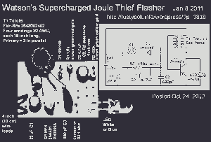
This picture and schematic were intended for posting on my Watson's blog, but it did not get published. The circuit schematic in question likely includes various electronic components arranged to perform a specific function. Typically, such schematics are used to...
The circuit is designed for inductive loads, specifically within a thyristor power unit, such as a three-phase step-down DC motor speed control and other applications. It is capable of delivering sufficient output power to trigger a thyristor rated at...
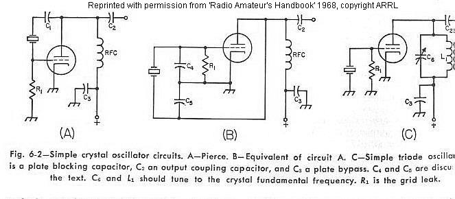
The frequency of a crystal-controlled oscillator is maintained with high precision through the use of a quartz crystal. The frequency is primarily determined by the dimensions of the crystal, particularly its thickness, while other circuit parameters have minimal impact....

This circuit diagram of a digital clock utilizes six common anode seven-segment displays to indicate the time. It does not require microcontrollers or PICs for operation. The circuit operates using the MM5314 integrated circuit, functioning at either 50 Hz...
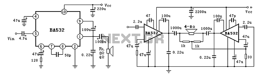
BA532 is a low-frequency power amplifier circuit designed for an output transformerless (OTL) application, capable of delivering up to 5.8W of output power. It features built-in protection against load short-circuits, over-voltage, and over-temperature conditions. The amplifier is housed in...
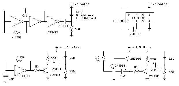
The LED flasher circuits operate on a single 1.5-volt battery. The circuit on the upper right utilizes the popular LM3909 LED flasher IC and requires only a timing capacitor and an LED. The LED flasher circuit using the LM3909 integrated...
Warning: include(partials/cookie-banner.php): Failed to open stream: Permission denied in /var/www/html/nextgr/view-circuit.php on line 713
Warning: include(): Failed opening 'partials/cookie-banner.php' for inclusion (include_path='.:/usr/share/php') in /var/www/html/nextgr/view-circuit.php on line 713