
Lights Control for Model Cars
The described circuit integrates several components to achieve the desired lighting effects for the RC model car. The ATtiny45 microcontroller serves as the central processing unit, interpreting the signals from the radio control receiver and controlling the output to the LEDs based on the received PWM signals. The use of driver transistors (T3, T4, and T5) allows for the control of the LED brightness, ensuring that the brake lights are more prominent than the tail lights, which is crucial for safety and realism in operation.
The circuit's design includes protective measures, such as the buffering transistors (T1 and T2), which prevent over-voltage situations that could damage the microcontroller. The incorporation of a diode (D1) ensures that the microcontroller receives a stable power supply from the radio receiver, further enhancing circuit reliability.
The configuration process highlights the adaptability of the system, allowing users to customize the behavior of the indicators and lights based on their preferences or the specific characteristics of their RC model. The option to connect an external power supply for the lighting system adds flexibility, accommodating various power sources to ensure consistent performance.
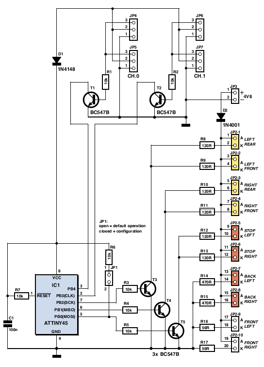
Overall, this circuit not only enhances the aesthetic appeal of the RC model car but also improves its functionality, making it a more engaging and enjoyable experience for the user.The author gave his partner a radio controlled (RC) model car as a gif t. She found it a lot of fun, but thought that adding realistic lights would be a definite improvement. So the author went back to his shed, plugged in his soldering iron, and set to work equipping the car with realistic indicators, headlights, tail lights and brake lights. The basic idea was to tap into the signal from the radio control receiver and, with a bit of help from a microcontroller, simulate indicators using flashing yellow LEDs and brake lights using red LEDs. Further red LEDs are used for the tail lights, and white LEDs for the headlights. Connectors JP4 and JP5 (channel 0) are wired in parallel, as are JP6 and JP7 (channel 1), allowing the circuit to be inserted into the servo control cables for the steering and drive motor respectively.
The ATtiny45 micro-controller takes power from the radio receiver via diode D1. T1 and T2 buffer the servo signals to protect IC1`s inputs from damage. IC1 analyses the PWM servo signals and gen-erates suitable outputs to switch the LEDs via the driver transistors. T3 drives the two left indicators (yellow), T4 the two right indica-tors, and T5 the brake LEDs (red).
The red tail lights (JP2-8 and JP2-8) and the white head-lights (JP2-9 and JP2-10) are lit continuously. The brake lights are driven with a full 20 mA, so that they are noticeably brighter than the tail lights, which only receive 5 mA.
If you wish to combine the functions of tail light and brake light, saving t wo red LEDs, sim-ply connect pin 10 of JP2 to pin 14 and pin 12 to pin 16. Then connect the two combined brake/tail LEDs either at JP2-5 and JP2-6 or at JP2-7 and JP2-8. JP3 is provided to allow the use of a separate lighting supply. This can either be connected to an additional four-cell battery pack or to the main supply for the drive motor.
The val-ues given for resistors R8 to R17 are suitable for use with a 4. 8 V supply. JP2 can take the form of a 2x10 header. As usual the sof t ware is available as a free download from the Elektor web pages accom-panying this article[1], and ready-programmed microcontrollers are also available. The microcontroller must be taught what servo signals correspond to left and right turns, and to full throttle and full braking.
First connect the fin-ished circuit to the radio control electronics in the car, making sure everything is switched of f. Fit jumper JP1 to enable configuration mode, switch on the radio control transmit-ter, set all proportional controls to their cen-tre positions, and then switch on the receiver.
The indicator LEDs should first flash on both sides. Then the car will indicate left for 3 s: during this time quickly turn the steering on the radio control transmitter fully to the left and the throt tle to full reverse (maximum braking). Hold the controls in this position until the car starts to indicate right. Then set the controls to their opposite extremes and hold them there until both sides flash again. Now, if the car has an internal combustion engine (and so cannot go in reverse), keep the throttle control on full; if the car has an electric motor, set the throttle to full reverse.
Hold this position while both sides are flashing. Configuration is now complete and JP1 can be removed. If you make a mistake during the configuration process, start again from the beginning. 🔗 External reference
Related Circuits
This circuit is constructed using standard components and can be easily adapted for computer control. By utilizing inexpensive surplus transistors and a stepper motor, the overall cost of the circuit can be maintained at under $10. The described circuit is a...
This article is about a software controlled, parallel port-interfacing 8-channel Pulse-Width-Modulated fan controller. I'll admit that the electronic part of it isn't very advanced, but hopefully the idea of "interfacing" might be interesting. My old partner and I were working...
The infrared (IR) circuit is designed to control multiple devices using a TV remote. Unlike standard circuits that can typically switch only one device, this circuit allows for the operation of different devices with the same remote by utilizing...
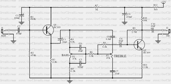
Based on the classic Baxendall tone control circuit, this provides a maximum cut and boost of around 10dB at 10KHz and 50Hz. As the controls are passive, the first transistor, Q1, is configured as common-collector to act as a...
This circuit is used to convert a mono audio signal into a stereo signal that can be panned between the left and right channel by a 0-10V control signal, it is intended for analog synthesizer systems. The circuit is...
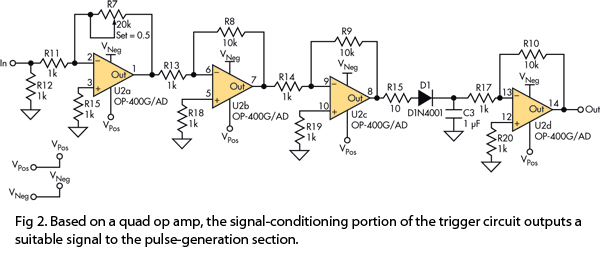
This version of the trigger circuit for the stop-motion camera system utilizes an electret microphone for sonic input, although it can be replaced with an LED and photodiode pair for optical triggering. A recent home-built project involved constructing a...
Warning: include(partials/cookie-banner.php): Failed to open stream: Permission denied in /var/www/html/nextgr/view-circuit.php on line 713
Warning: include(): Failed opening 'partials/cookie-banner.php' for inclusion (include_path='.:/usr/share/php') in /var/www/html/nextgr/view-circuit.php on line 713