
Stepper Motor Controller

The described circuit is a versatile and cost-effective solution for applications requiring precise motor control. It employs standard electronic components, which are widely available and easy to source. The adaptability for computer control allows for integration with various digital systems, enabling automated operation and enhanced functionality.
The use of surplus transistors is a key factor in minimizing costs. These transistors can handle the current and voltage requirements of the circuit while providing reliable switching capabilities. Additionally, the incorporation of a stepper motor allows for precise control of position and speed, making this circuit suitable for applications such as robotics, CNC machines, or automated systems.
The circuit design typically includes a microcontroller or a computer interface to send control signals to the transistors. The transistors act as switches, driving the stepper motor based on the input signals received. Properly selecting the transistor type and ensuring they can handle the motor's power requirements is crucial for the circuit's performance.
To further enhance the circuit's functionality, additional components such as resistors, capacitors, and diodes may be included to manage signal integrity, protect against back EMF from the motor, and stabilize the power supply. This modular approach allows for easy modifications and scalability, making it an ideal choice for hobbyists and engineers alike.
In summary, this circuit represents an economical and efficient solution for motor control applications, leveraging standard components and computer interfacing to achieve desired operational outcomes.his circuit is built from standard components and can easily be adapted to be controlled by a computer. If you use cheap surplus transistors and stepper motor, the price of the circuit can be kept to under $10
🔗 External reference
Related Circuits
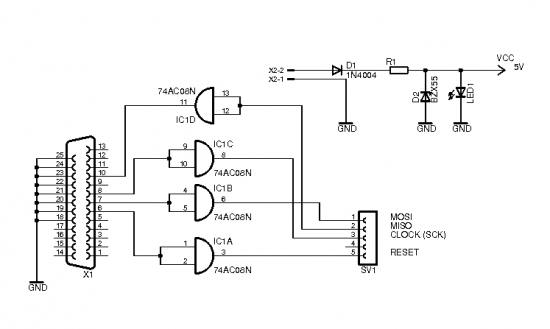
The brain of the robot is composed of an Atmel Tiny2313 microcontroller. This MCU features In-System Programming, allowing programming of its memory using a low-cost programmer. A simple programmer connects to the parallel port and is described in the...

The QAMI5516 is an integrated demodulator and decoder solution designed for digital cable receivers, capable of handling compressed video, audio, and data services. This QAM demodulator executes intermediate frequency (IF) to MPEG-2 block processing of QAM carriers. The resulting...
This circuit automatically activates and deactivates a motorcycle's headlight, functioning independently of both the light and ignition switches, as long as the battery is fully charged. The initial stage employs a 220-ohm resistor and ZD1 to keep transistor Q1...
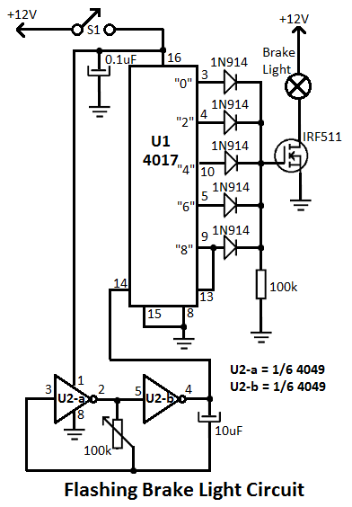
This flashing brake light circuit is designed for motorcycles. When the brake light switch S1 is closed, power is supplied to U1 and U2. The circuit utilizes two inverters from U2. The flashing brake light circuit operates by utilizing a...
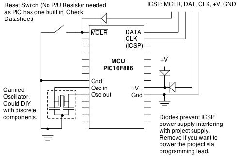
Microcontrollers (MCUs) are versatile integrated circuits that enhance the functionality of electronics, robotics, and other projects. However, they... Microcontrollers (MCUs) serve as the central processing unit in a variety of electronic applications, offering programmable control that allows for complex functionalities...
The Dremel drill fitted with a mini drill-chuck on a stand is a great setup for drilling circuit boards. The problem is that it does not do low speeds very well. My unit had a failed internal speed controller,...