
Linear scale ohmmeter

The described circuit utilizes a single preset resistor to streamline the calibration process across multiple ranges. This design choice minimizes the complexity involved in adjusting the meter for different resistance values. The inclusion of diode clamping serves a critical protective function, safeguarding the meter's internal components from potential overvoltage conditions that could arise if the unknown resistor's value surpasses the selected measurement range.
Upon assembly, a 10 K precision resistor is placed in the designated test position, denoted as R*. The meter is configured to the 10 K range, allowing for accurate measurement of resistance values close to this standard. The adjustment of RV1 is crucial, as it calibrates the meter to ensure that it reads full-scale deflection when the known resistance is applied. This process not only ensures accuracy but also enhances the reliability of measurements taken with the device.
The schematic for this circuit would typically include a resistor labeled R*, the preset resistor, the variable resistor RV1, and the necessary diodes for clamping. The circuit layout should ensure that the diode connections are positioned correctly to prevent reverse current flow, thereby protecting sensitive components. Additionally, clear labeling of all components and their respective connections is essential for ease of understanding and troubleshooting during assembly or maintenance. Proper grounding and power supply connections must also be considered to ensure stable operation of the meter. Overall, the design is intended to deliver precise resistance measurements while maintaining robustness against potential electrical hazards.One preset resistor is used for all the ranges, simplifying the setting up. Diode clamping is included to prevent damage to the meter if the unknown resistor is higher than the range selected When the meter has been assembled, a 10 K precision resistor is placed in the test position, R*; the meter is set to the 10 K range and RVl is adjusted for full scale deflection. 🔗 External reference
Related Circuits
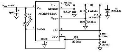
The ADM666A application note provides a detailed explanation of a low-cost battery charger circuit, including maximum output voltage, charge termination voltage calculation, battery voltage level monitoring, and circuit efficiency optimization. The ADM666A utilizes an NPN transistor and a P-channel...
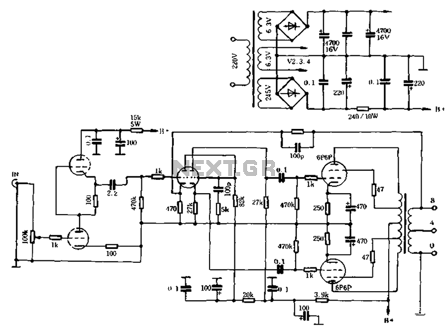
The self-generated bias amplifier tube is designed for each tube individually to alleviate the challenges faced by amateur conditions in paired amplifiers. It includes a separate DC filament power supply, which minimizes the risk of induced cross-linking and enhances...
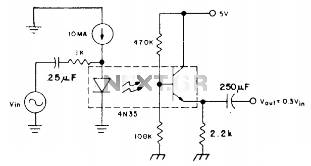
The coupler is biased in the linear region using a 10 mA DC bias on the infrared emitting diode (IRED) and a voltage divider connected to the base of the phototransistor. This configuration allows the photodiode current to flow...
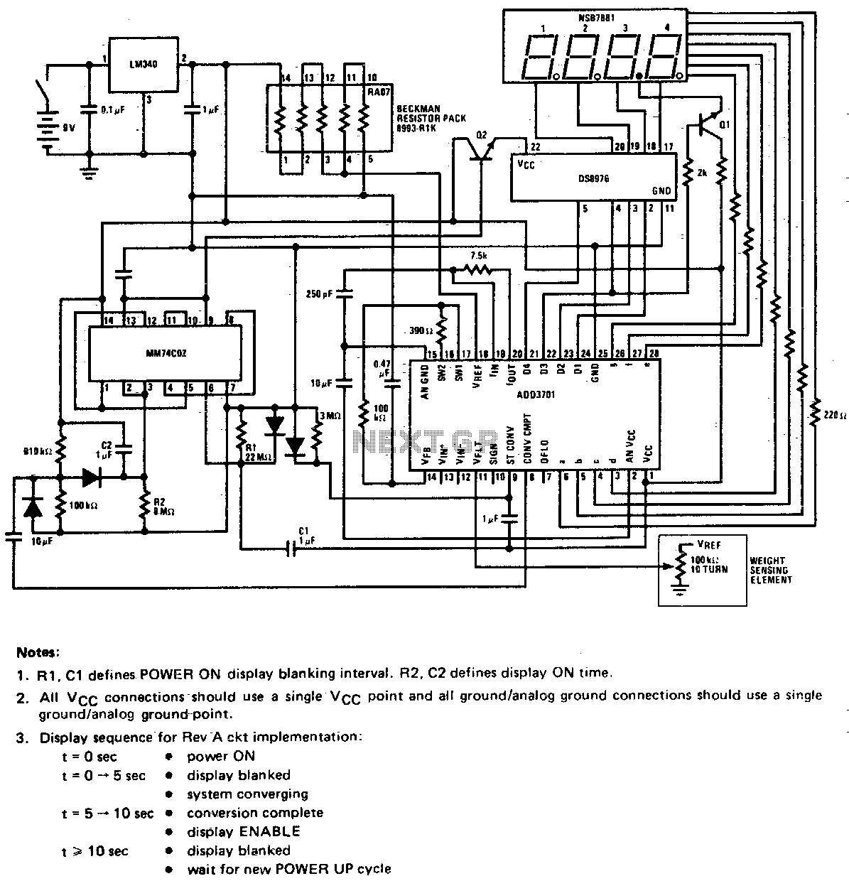
This circuit utilizes a potentiometer as the weight sensing element. An object placed on the scale displaces the potentiometer wiper by an amount proportional to its weight. The conversion of the wiper voltage to digital information is carried out,...
High linearity analog optocouplers offer the versatility needed to address a variety of analog isolation requirements. For high voltage applications, these optocouplers can effectively transmit analog signals between high voltage and low voltage areas without introducing distortion. This article...

The 60 Watt linear amplifier is a straightforward all-solid-state circuit utilizing the power MOSFET IRF840. The IRF series of power transistors are available in various voltage and power ratings. A single IRF840 can handle a maximum power output of...