
Liquid-Level Sensor
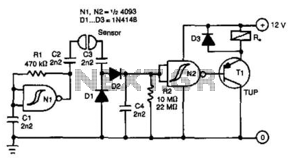
The circuit operates by detecting the presence of an AC signal, which is indicative of potential corrosion issues in metallic structures such as pipelines or storage tanks. The AC-sensing mechanism typically involves a transformer or a current sensor that captures the AC signal from the environment.
Once the AC signal is acquired, it is fed into a rectifier circuit, which converts the alternating current (AC) into direct current (DC). This rectification process is crucial as it allows the subsequent components of the circuit, particularly the transistor, to operate effectively.
The rectified DC voltage is then used to bias a transistor, which acts as a switch in this application. The choice of transistor is important; it must be capable of handling the current required to activate the relay. Commonly, a bipolar junction transistor (BJT) or a field-effect transistor (FET) is used for this purpose.
When the AC signal is present and the transistor is activated, it allows current to flow through the relay coil. The relay serves as an electromechanical switch that can control larger loads, such as a power supply or a protective device, that can mitigate corrosion effects.
The relay contacts can be configured to either disconnect power from the affected area or activate a protective measure, such as an impressed current system or a cathodic protection system, which helps in reducing the risk of corrosion.
Additional components may include resistors for biasing the transistor, diodes for protecting against back EMF from the relay coil, and capacitors for filtering purposes to ensure stable operation of the circuit. Overall, this circuit design effectively utilizes an AC signal to control corrosion through a relay-driven mechanism. This circuit uses an ac-sensing signal to eliminate electrolytic corrosion. The ac signal is rectified and used to driv e a transistor that controls a relay. 🔗 External reference
Related Circuits

The electronic device detects proximity, measuring the user's distance quickly. Currently, most proximity sensors available on the market have a relatively short detection range of approximately 1 to 10 cm. The use of infrared LEDs in multipulse mode for...
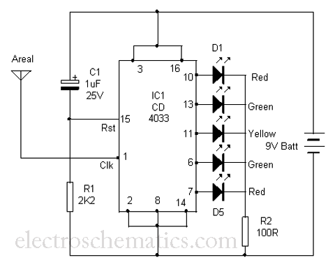
This is a simple tool designed to measure the level of radiation emitted by electrical or electronic devices. The circuit utilizes LEDs to create a running light pattern when it detects electromagnetic radiation from a source. It can detect...

This design circuit is for a temperature sensor that utilizes an LM335 integrated circuit (IC) to convert ambient temperature into an equivalent output voltage. The output voltage of the LM335 increases by approximately 10 mV for every 1 degree...
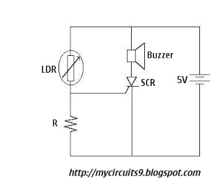
The Light Dependent Resistor (LDR) is a variable resistor whose resistance decreases as light intensity increases. Under normal light conditions, the resistance of the LDR is sufficiently high, resulting in an inadequate voltage across resistor R to activate the...
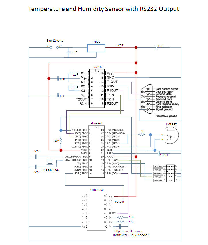
This is an affordable method for measuring temperature and humidity with a computer interface, designed as an entry-level project for high school students on a limited budget. The project involves the integration of a temperature and humidity sensor, such as...

This is a low-current temperature sensor with a single-wire output. The number of pins required to interface with a microprocessor is minimized by this design. The low-current temperature sensor operates efficiently by utilizing a single-wire communication protocol, which significantly reduces...