
Radiation Sensor Circuit
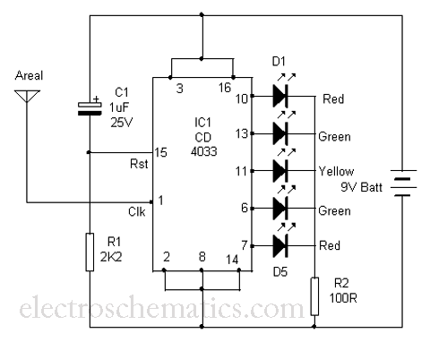
The circuit is primarily based on the CD4033 decade counter, which is a CMOS integrated circuit designed for counting applications. It features a binary counting capability, which can be translated into visual signals through the LEDs. The circuit operates by capturing electromagnetic radiation, which induces a clock signal at the input pin of the CD4033. The sensitivity of the IC allows it to detect even weak signals, making it effective for monitoring radiation from common household appliances.
The LED outputs are configured in such a way that they light up in succession, creating a visual representation of the radiation intensity. The arrangement of the LEDs can be designed to provide a clear indication of the radiation level, with more LEDs lighting up as the radiation increases. The timing of the LED sequence is determined by the frequency of the clock signal generated by the radiation, which is influenced by the distance from the source.
Capacitor C1 and resistor R1 play a crucial role in resetting the IC after each cycle. This reset mechanism ensures that the counter returns to its initial state, allowing for continuous monitoring without manual intervention. The choice of values for C1 and R1 is critical, as they determine the timing of the reset and the responsiveness of the circuit to changes in radiation levels.
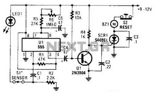
To enhance the usability of the device, it may incorporate a power supply circuit, ensuring that it operates reliably without fluctuations. Additionally, a housing could be designed to protect the circuit and provide a user-friendly interface, such as a calibration feature or a scale indicating radiation levels. Overall, this radiation detection tool serves as a practical solution for assessing the safety of electronic devices in various environments.Here is a simple tool to check the degree of radiation from an electric or electronic instrument. The LEDs in the circuit will give a running light pattern at the moment the circuit senses electromagnetic radiation from the device. It can detect radiation from the Computer or TV from a distance of 2 feet or more. ICCD4033is the decade counter with 7 segment display driver. It has seven outputs to drive LEDs or Seven segment display. The clock input (pin1) of IC isvery sensitiveand readily accepts energy from the electromagnetic radiation even from a long distance. This property of the IC CD4033 is exploited here to measure the intensity of radiation. The reset pin 15 of IC is connected to C1 and R1 to reset the IC after completing a cycle. So that the functioning of IC continues till the input pulses cease. Bring the areal close to the TV or CRT monitor of computer. All the LEDs light up one by one giving a running pattern. The speed of running light depends on the strength of radiation. Move away the unit from the monitor. As the diastance increases, speed of running light decreases. Finally all the LEDs stop glowing. This is the point without the radiation. Check all the electric instruments and mains wiring using the device and find out how much radiation is emitting.
🔗 External reference
Related Circuits
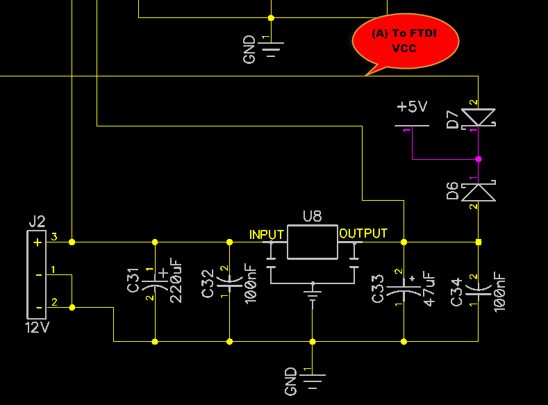
When only the voltage regulator (VR) supplies power to the circuit, the microcontroller unit (MCU) will receive power from the +5V bus, while the FTDI chip will only receive VCCIO. At the midpoint of the voltage divider formed by...
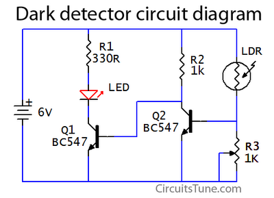
This is a basic dark detector or sensor circuit diagram based on a photoresistor (LDR) and a few components. The dark detector circuit utilizes a photoresistor (LDR) as the primary sensing element. The LDR is a light-dependent resistor that changes...
When this thermometer is utilized in a room environment, it operates intermittently, maintaining this operational state within the temperature measurement circuit due to the stable internal temperature. The astable multiresonance oscillator is composed of transistors VT1 and VT2, forming...

This 1000-watt power inverter circuit diagram is based on the MOSFET RF50N06. For increased power output, additional MOSFETs can be paralleled with the RF50N06. These MOSFETs are rated for 60 volts and 50 amps. It is essential to connect...
A typical two high-pass filter circuit. A high-pass filter (HPF) is an electronic circuit that allows signals with a frequency higher than a certain cutoff frequency to pass through while attenuating signals with frequencies lower than the cutoff frequency. A...
The alarm circuit utilizes a single 555 oscillator/timer (U1) that functions in both the alarm-trigger circuit and the entry-delay circuit. In this configuration, the trigger input of U1 at pin 2 is maintained in a high state through resistor...
Warning: include(partials/cookie-banner.php): Failed to open stream: Permission denied in /var/www/html/nextgr/view-circuit.php on line 713
Warning: include(): Failed opening 'partials/cookie-banner.php' for inclusion (include_path='.:/usr/share/php') in /var/www/html/nextgr/view-circuit.php on line 713