
Temperature & Humidty sensor Using AVR Microcontroller
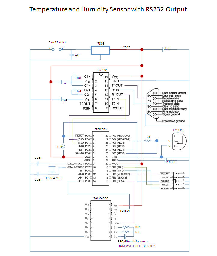
The project involves the integration of a temperature and humidity sensor, such as the DHT11 or DHT22, which are both cost-effective and widely used in educational settings. These sensors provide digital output, making it easier for students to interface with microcontrollers or computers. A microcontroller, like the Arduino Uno, can be utilized to read the sensor data and transmit it to a computer for further analysis or display.
The circuit design includes connecting the sensor's data pin to a digital input pin on the microcontroller, with appropriate pull-up resistors if necessary. Power supply connections must be established, ensuring that the sensor operates within its specified voltage range, typically 3.3V to 5V.
To facilitate the computer interface, a USB connection can be implemented through the microcontroller, allowing for serial communication. This enables the temperature and humidity data to be sent to a computer application, which can display the readings in real-time.
The software component of the project involves writing a simple program in the Arduino IDE that initializes the sensor, reads the data at regular intervals, and sends it to the computer. Students can also explore data logging by storing the readings in a file for later analysis.
This project not only introduces students to fundamental concepts in electronics and programming but also provides practical experience in working with sensors and data communication, making it an ideal educational tool for beginners.This is a low cost way of measuring temperature and humidity with a computer interface and is intended to be an entry level project for high school students on a tight budget. 🔗 External reference
Related Circuits
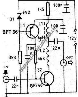
This design presents a simple antenna amplifier electronic circuit project, which can be utilized based on the provided circuit diagram. The antenna amplifier operates effectively within a frequency range of 1 to 300 MHz. It is suitable for high...
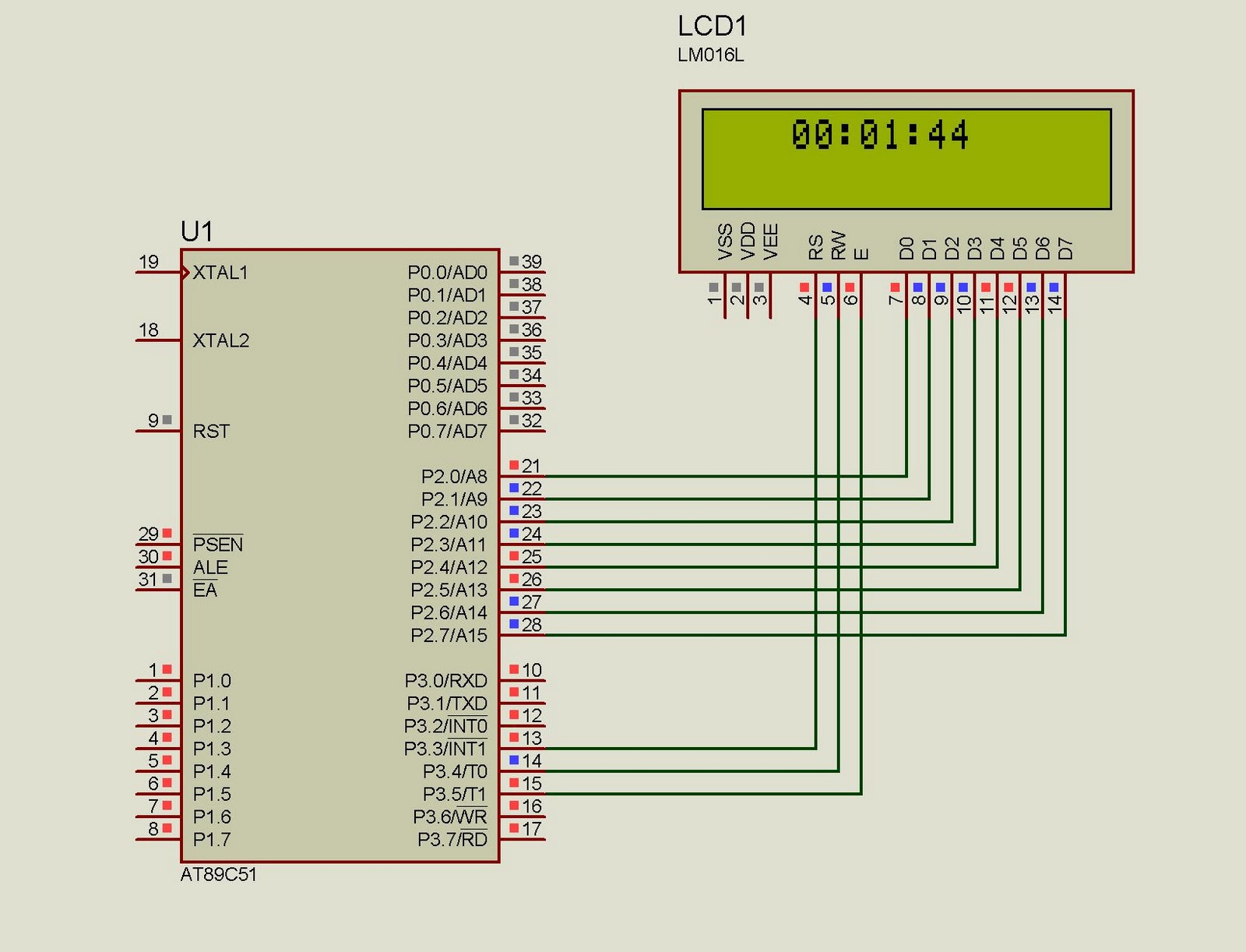
This project implements a real-time clock using the 89C51 microcontroller. The clock's data format is hours:minutes:seconds, which is displayed on a 16x2 LCD. The code has been tested and compiled using the Keil uVision compiler. The circuit diagram for...
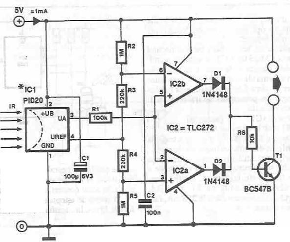
This infrared detector circuit utilizes the PID20 integrated circuit manufactured by Siemens, which converts thermal radiation into electrical impulses. It includes an operational amplifier and several electronic components. The output signal at pin 3 is compared to a reference...
Industrial-grade clear glass sensor modules are widely available but often not accessible to the average electronics hobbyist. The simple clear glass sensor... Industrial-grade clear glass sensor modules are specialized devices designed for various applications, including environmental monitoring, industrial automation, and...
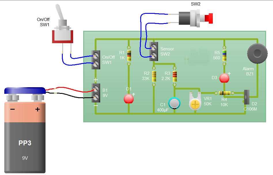
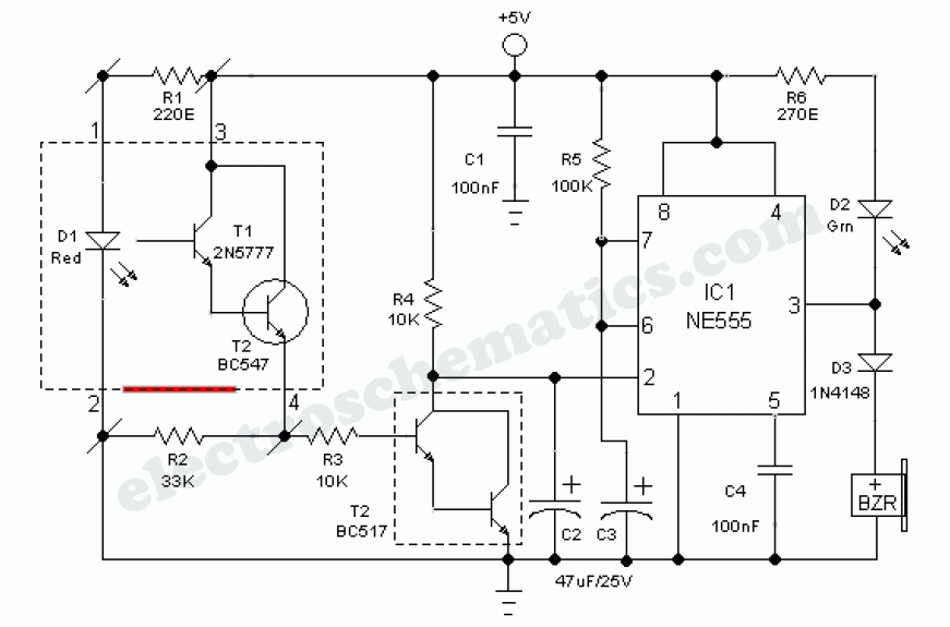
When the sensor switch SW2 is pressed, the LED D3 and the alarm are activated for a certain duration. The timing of the circuit is determined by the resistor R3 and capacitor C1. Additional details regarding the RC circuit...
This document describes a PLL FM transmitter utilizing the LMX1601 and either the ATtiny2313 or AT90S2313 microcontrollers. A common feature of previous low-power FM transmitters developed over the years is that their operating frequency is determined by an LC...