
Liquid or Water Sensor Circuit with Alarm
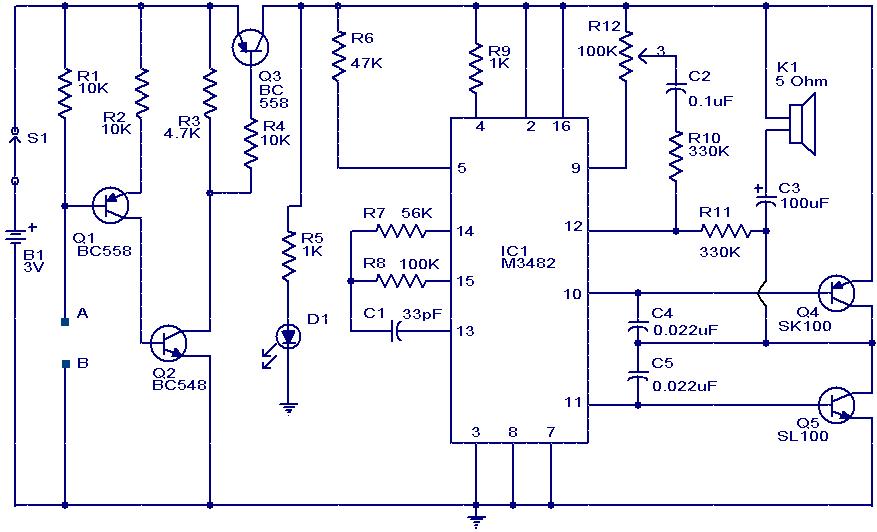
The water sensor circuit typically consists of a few essential components, including a pair of conductive probes, a comparator circuit, and an alarm system. The probes are placed in the environment where liquid detection is desired. When water or another conductive liquid comes into contact with the probes, it completes the circuit between them.
The comparator circuit, often built using an operational amplifier (op-amp), continuously monitors the voltage across the probes. In a dry state, the resistance between the probes is high, resulting in a low voltage reading. When liquid is present, the resistance decreases, causing the voltage to rise above a predetermined threshold. This change is detected by the comparator.
Upon detecting the presence of liquid, the comparator output switches state, triggering the alarm system. The alarm can be an audible buzzer, LED indicator, or other alert mechanisms, depending on the design requirements. Additional features may include adjustable sensitivity to accommodate different types of liquids or environmental conditions.
Power supply considerations are also crucial for the circuit's operation. Typically, a low-voltage power source, such as a battery or a DC power supply, is used to ensure safe operation. The circuit can be further enhanced by incorporating a microcontroller for more advanced functionalities, such as data logging or remote notifications.
Overall, this water sensor circuit serves as a practical solution for hobbyists seeking to create simple yet effective liquid detection systems for various applications, including leak detection, overflow prevention, and agricultural monitoring.This is just a fun/hobby circuit which can be used as a water sensor circuit or a liquid sensor circuit.What it does is sound an alarm in presence of water/liquid at its probes.. 🔗 External reference
Related Circuits
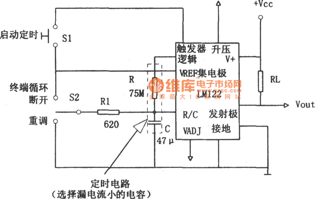
In this figure, S1 initiates the timing process, and once the timer is activated, toggling this switch will not impact the timing operation. S2 serves as the OFF switch located in the center; toggling this switch allows the timer...
This index is organized alphabetically by each word (excluding prepositions). For instance, the "Frost Alarm" will be listed under both "A" and "F". To efficiently locate a circuit, utilize the top index or employ your browser's search feature. In...
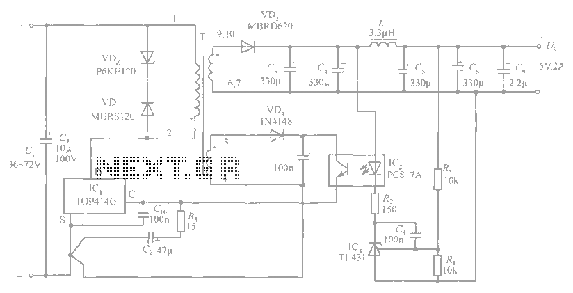
The circuit diagram includes an input filter capacitor C1 and a primary clamp composed of VDz and VD1. The resistor R1 is connected to the control terminal. C2 serves as a bypass capacitor. The TOP414GC-S is connected in parallel...
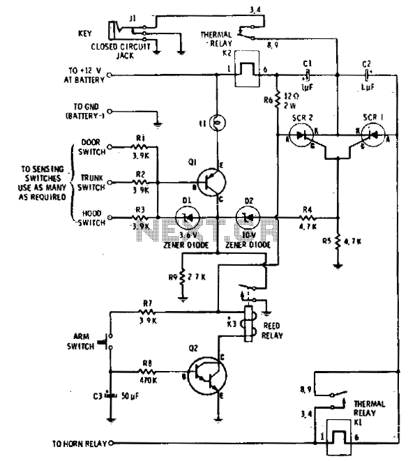
The circuit features an integrated self-arming capability. The driver turns off the ignition, presses the arm button on the Computalarm, and exits the vehicle. Within 20 seconds, the alarm arms itself automatically. The circuit is designed to detect the...
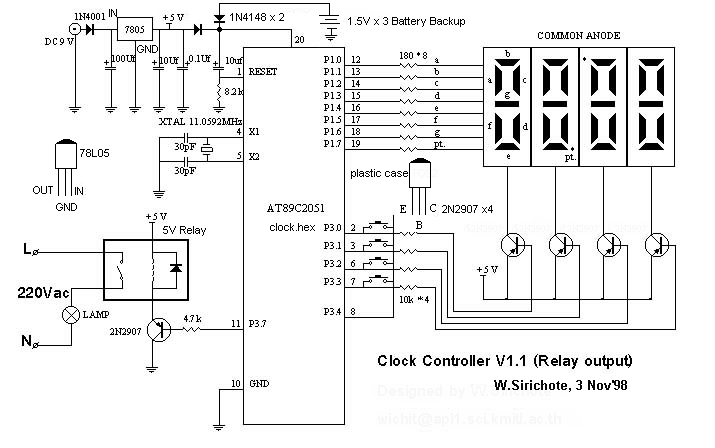
The Clock Controller was designed as an exemplary application of the C programming language to manage timer0 interrupts, control a 7-segment LED display, and perform keypad scanning. It offers a 1-bit sink current output suitable for driving devices such...
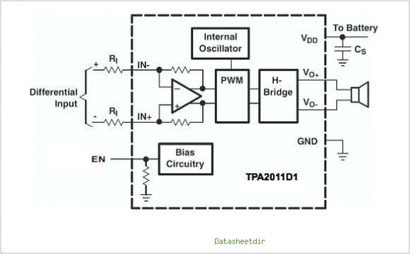
The TPA3007D1 is a 6.5-W mono bridge-tied load (BTL) class-D audio power amplifier featuring high efficiency, which eliminates the need for heat sinks. This amplifier can drive 8-ohm speakers with only a ferrite bead filter required to reduce electromagnetic...
Warning: include(partials/cookie-banner.php): Failed to open stream: Permission denied in /var/www/html/nextgr/view-circuit.php on line 713
Warning: include(): Failed opening 'partials/cookie-banner.php' for inclusion (include_path='.:/usr/share/php') in /var/www/html/nextgr/view-circuit.php on line 713