
Clock Controller circuit
The Clock Controller circuit is designed for efficient operation in applications requiring timer control, display, and user input. The use of a common anode configuration for the 7-segment display allows for simplified control of the segments by grounding the appropriate pins. The implementation of the 2N2907 PNP transistors as switches for the display ensures that sufficient current is supplied to illuminate the segments while maintaining low power consumption.
The keypad scanning mechanism is executed through a systematic approach, where the microcontroller sequentially activates each pin connected to the keypad. This technique not only minimizes the number of required I/O pins but also allows for rapid detection of key presses. The logic '0' shifting every 10 ms ensures that the system remains responsive to user input while maintaining a stable display.
In terms of output control, the inclusion of a relay driven by a 2N2907 transistor provides a versatile solution for controlling external devices. The use of a solid-state relay for higher current applications further enhances the circuit's capability, allowing it to interface with various load types without mechanical wear associated with traditional relays.
Overall, the Clock Controller represents a well-rounded design that integrates software and hardware elements effectively, serving as a valuable reference for similar projects involving 7-segment displays, keypad interfaces, and relay control. The accompanying software, along with the hardware design, offers a comprehensive framework for developers and engineers looking to implement similar functionalities in their electronic circuits.The Clock Controller was designed to be an exemplary of using `C` language to control timer0 interrupt, 7-segment LED and keypad scanning. It provides 1-bit sink current driving output, for driving a relay, opto-triac, say. Many projects requiring 7-segment display and keypad interfacing may get the idea from the Clock circuit and software.
Fi gure 1 depicts a circuit diagram of the Clock Controller V1. 1. P10-P1. 7 drives 7-segment common anode LED with sink current. P3. 0-P3. 3 also drives a base pin of 4-PNP transistor, 2n2907 with sink current. As shown in the figure, the 2nd 2-digit LED that connected to P3. 2 and P3. 3 is rotated 180 degrees to the 1st 2-digit allowing the pt. segment to be used for 1 second blinking. P3. 0-P3. 3 also connects four momentary switchs while the other legs are tied to input port P3. 4. During display and key switch scanning, a logic `0` is shifted from P3. 0 to P3. 3 every 10ms, if there was a key pressed, P3. 4 then became low. P3. 7 is a 1-bit sink current driving, an example in the circuit uses a 2n2907 to drive a small electromechanical relay 5V, say. The program clock. c was written in ‘C ’ language and was complied by Micro-C Compiler from Dunfiled Development Systems.
The memory model is TINY. The hex file of clock. c suitable for downloading by Easy-Downloader is clock. hex. I suggest to use a zero switch solid-state relay for driving heavy loads (>10A). Most solid state relays`s input can be drived with 3-30Vdc without any problems. 🔗 External reference
Related Circuits
Class D amplifiers are significantly more efficient than traditional amplifiers; however, this high efficiency is accompanied by increased noise and distortion. The frequency and time-domain characteristics of a Class D amplifier, including its output filter, can be evaluated using...
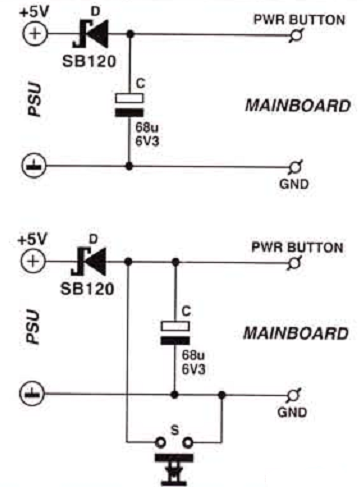
Many enthusiasts utilize their PCs as data loggers, controllers, or web servers. In such instances, it is crucial to ensure that the machine remains powered for as much time as possible, even during a power outage or if the...
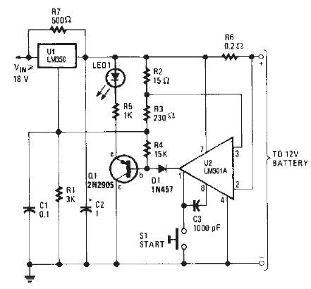
The LM350 car battery charger circuit is a high-performance device designed to efficiently charge gelled lead-acid batteries and automatically terminate the charging process once the battery reaches full charge. This circuit provides a charging current of 2A when the...
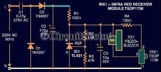
This document presents an infrared remote control tester circuit that can be constructed at a low cost. The circuit is built around the infrared receiver module TSOP1738. The state of the remote control can be observed through the sound...

The TPS61200 specifications indicate that GND serves as the control/logic ground, while PGND is designated as the power ground. However, this distinction is not accurately represented in the symbols used in the diagram. There is also confusion regarding the...
PC parallel port can be very useful I/O channel for connecting your own circuits to PC. The PC's parallel port can be used to perform some very amusing hardware interfacing experiments. The port is very easy to use when...
Warning: include(partials/cookie-banner.php): Failed to open stream: Permission denied in /var/www/html/nextgr/view-circuit.php on line 713
Warning: include(): Failed opening 'partials/cookie-banner.php' for inclusion (include_path='.:/usr/share/php') in /var/www/html/nextgr/view-circuit.php on line 713