
lithium battery charger
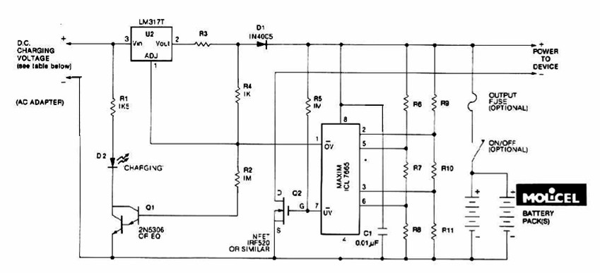
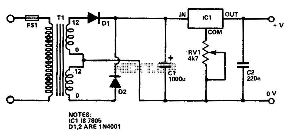
The lithium battery charger circuit is engineered to accommodate various configurations of lithium battery packs, allowing for flexibility in applications ranging from consumer electronics to larger battery systems. The LM317T voltage regulator is a linear regulator that provides a stable output voltage, adjustable via external resistors, which can be tailored to meet the specific voltage requirements of the battery pack being charged.
The IC L7665 serves a critical role in monitoring the battery voltage, ensuring that the charging process remains within safe limits. It provides overvoltage and undervoltage protection, which is essential for the longevity and safety of lithium batteries. By signaling the microprocessor when the voltage exceeds or drops below predetermined thresholds, it helps prevent potential damage to the cells.
During the charging phase, the circuit maintains a constant current of 60 mA, which is optimal for AA lithium cells. This controlled charging rate is crucial for preventing overheating and extending battery life. The cutoff voltage of 2.4 V per cell is a standard threshold for lithium batteries, marking the point at which charging should cease to avoid overcharging, which can lead to thermal runaway and other safety hazards.
Overall, this charging system is a reliable solution for managing the charging of multi-cell lithium battery packs, ensuring both performance and safety through careful voltage regulation and monitoring. The design is suitable for integration into various electronic devices requiring efficient and safe battery charging solutions.The charging system shown is made for multi-cell lithium battery packs of two to six series-connected cells or series/parallel arrangements. The schematic diagram come from circuit: Lithium Battery Charger power supply. Go to that page to read the explanation about above power supply related circuit diagram. This Lithium battery charger circuit is dedicated to charge lithium batteries. Ituses 2chips, voltage regulator LM317T and IC L7665 warns microprocessors ( Ps) of over voltage and unde rvoltage conditions. Charging is completed with a constant current of 60 ma for Aa cells to a cutoff voltage of 2. 4 V per cell, at which point the charge should be terminated. The. 🔗 External reference
Related Circuits
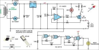
This circuit charges two NiCad cells with a constant current and features dual charging rates, voltage cutoff, and an audible alarm. The circuit is powered. This circuit is designed to efficiently charge two nickel-cadmium (NiCad) cells, utilizing a constant current...
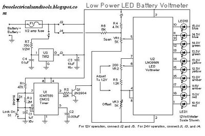
This is a low power voltmeter circuit designed for use with alternative energy systems that operate on 12V and 24V batteries. The voltmeter features an expanded scale that indicates small voltage steps within the 10 to 16 volt range...
Camping today often requires bringing various electronic devices for daily activities or entertainment. Frequently, a charge is needed for these devices. In modern camping scenarios, the reliance on electronic devices has significantly increased. Campers typically bring smartphones, tablets, GPS devices,...
The AAT1265 evaluation board serves as a platform for testing and evaluating the AAT1265 low voltage 2MHz step-up regulator. This evaluation board illustrates the recommended size and arrangement of external components necessary to maintain output voltage regulation for up...
This circuit provides a regulated output voltage ranging from 5 V to 15 V DC, which can be adjusted using a preset resistor. The current output can reach up to approximately 350 mA. An integrated circuit is utilized to...
The charger consists of two stages: The first is a capacitive voltage doubler, which uses a 555 timer IC driving a pair of transistors connected as emitter followers, which in turn drive the voltage doubler proper. The doubler has...