
LM Frequency Meter

The Model LM-13 Crystal Calibrated Frequency Indicating Equipment represents an important advancement in frequency measurement technology, tailored specifically for military applications. Its design prioritizes reliability and precision, essential for maintaining communication integrity within naval operations. The frequency range of 125 to 20,000 Kcs allows for versatility in tuning various radio equipment, making it indispensable for radio personnel.
The accuracy specifications of 0.02 percent and 0.01 percent at different frequency ranges ensure that operators can achieve precise frequency alignment, which is crucial for effective radio communication. The operational temperature range from -32 to +65 degrees Celsius further enhances its usability in diverse environmental conditions, ensuring consistent performance in varying climates.
The inclusion of a carrying case and canvas bag facilitates mobility, allowing operators to transport the equipment easily. The requirement for external power sources, such as the specified batteries, underscores the need for careful power management in field operations. The ability to connect to existing equipment, like the "RU" and "GF" series, highlights the LM-13's role in a broader ecosystem of radio technology, promoting interoperability among different devices.
Calibration is a critical aspect of the LM-13's functionality, as each unit is calibrated to ensure accuracy. The provision of a calibration book tied to the specific serial number of the unit emphasizes the importance of maintaining precise records for operational accountability and equipment reliability.
In summary, the Model LM-13 is a sophisticated piece of equipment that combines portability, accuracy, and reliability, making it a valuable tool for naval radio operators during its era. Its design reflects the needs of military communication systems, ensuring that personnel can effectively tune and maintain the frequency settings necessary for successful operations.The Model LM-13 Crystal Calibrated Frequency Indicating Equipment has been specially designed to provide a simple, accurate and reliable frequency indicating equipment of the crystal calibrated type for use in the (U. S. ) Naval radio service. It is adaptable for adjusting adjacent radio transmitters and receivers to any desired frequency within the
range from 125 to 20, 000 Kcs. The equipment provides accuracies of 0. 02 per cent in the 125 - 2000 Kcs range and 0. 01 per cent in the 2000 - 20000 Kcs band, at any ambient temperature in the range from -32 to plus 65 degrees Centigrade. The equipment comprised the Frequency Meter (CRR 74028), a carrying ase (CRR 10111), similar to the familiar BC221 bag and a canvas bag with strap, type CMQ-10111.
A set of 600 ohm headphones, 4 x 45 volt "B" battteries and 2 x 6 volt "A" batteries were also required. The whole unit weighed just under 40 Ibs. The filaments drew l2volts at 0. 67 amperes and the plate supply was 180 volts at 5 m. a. Often the LM frequency meters drew their operating power from the equipment they were to be used with.
Typical examples were the "RU" series of receivers, the "GF" series of transmitters (pre- command type equipment) and the RBM equipment. Each set, as in the case of the BC221, was separately calibrated and each was supplied with a calibration book bearing the same serial number.
A unit without the book is of limited use. Without the battery supply the units are quite compact and would have fitted quite easily beside the gear in a ham shack of the day. It was a simple matter to put together a power supply to operate the unit. Many of the LM models had provision for 12/24 volt operation and a choice of H. T. input voltages. The handbook indicates the unit was manufactured for the U. S Navy Bureau of Ships by Bendix Radio, Baltimore, Maryland. The original contract was dated 27 December, 1939. 🔗 External reference
Related Circuits
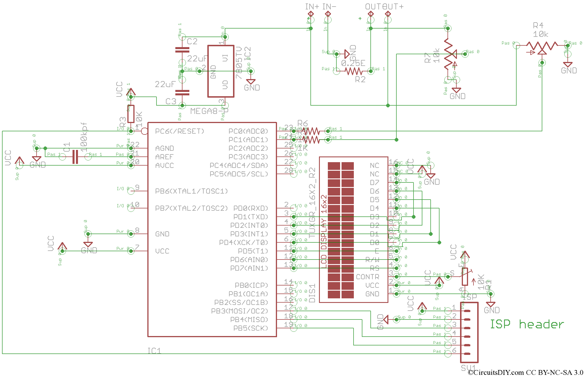
This is the V2 update of the Atmega8 Volt-Ammeter. This new version features several upgrades, including low power consumption, improved amperage display resolution while using a low-value drop resistor, and a much smaller PCB size of only 5cm x...
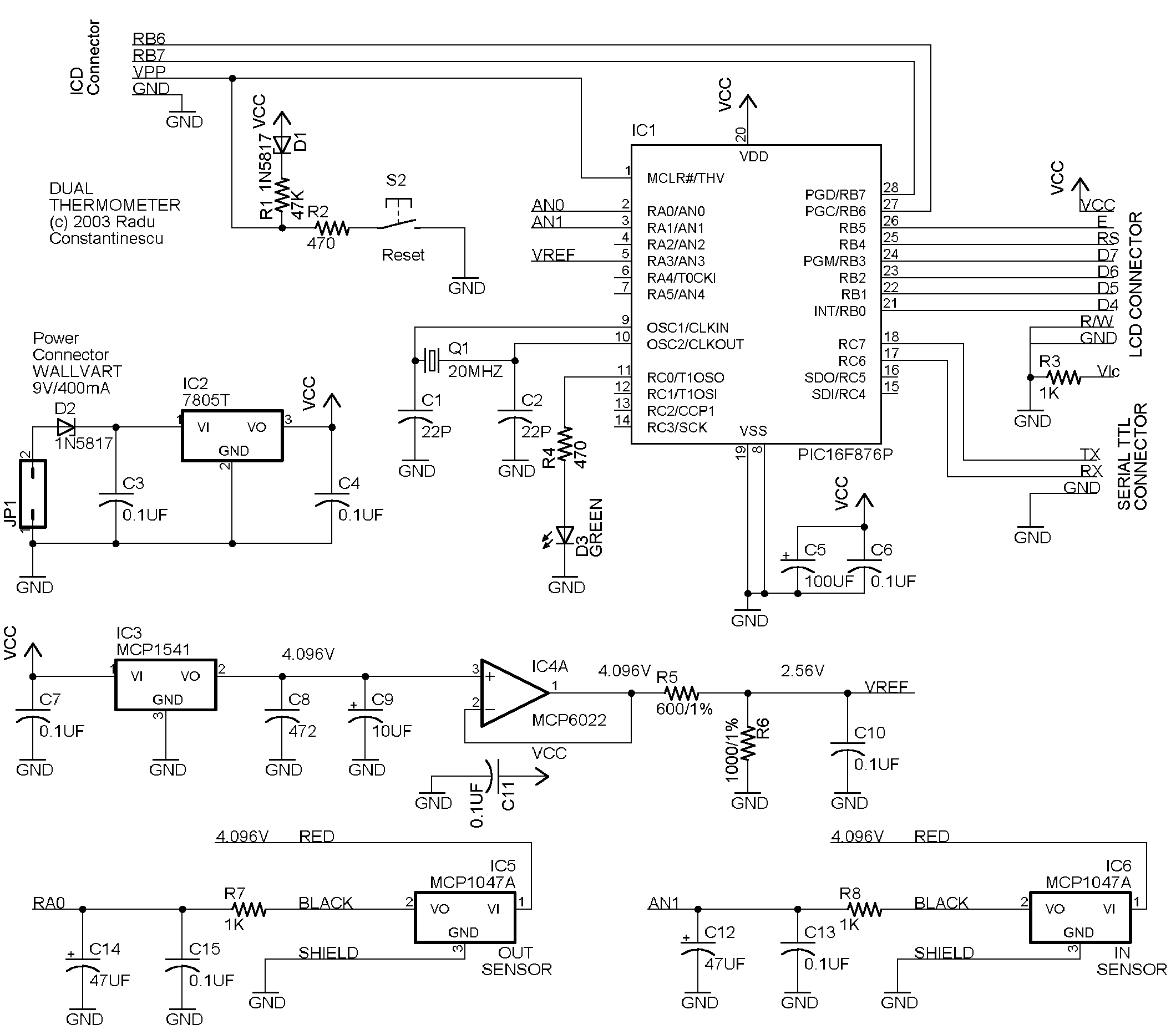
This circuit utilizes a PIC16F876 microcontroller, two MCP1047A temperature sensors, an MCP1541 voltage reference, and a MCP6022A operational amplifier. The display is a 2-row HD74780-based 2x16 character display (SII L1652BIJ2), though any HD74780 compatible display can be used. The...
Frequency converters are safeguarded against surges using surge protective devices, for which the maximum continuous operating voltage (Uc) must be considered. Frequency converters are critical components in various electronic applications, converting input frequencies to desired output frequencies. To ensure their...
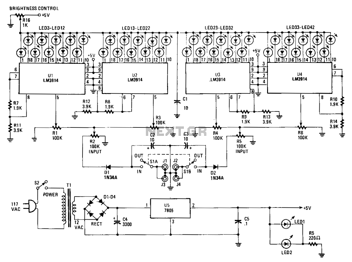
The Stereo Power Meter consists of two identical circuits and a power supply. Each circuit features two LM3914 display chips, which include 10 voltage comparators, a 10-step voltage divider, a reference voltage source, and a mode-select circuit that allows...
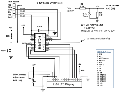
This project details the construction of a digital voltmeter utilizing a PIC microcontroller. A character-based HD44780 LCD display is employed to visualize voltage measurements. The microcontroller selected for this project is the PIC16F688, which features 12 I/O pins, with...

In this circuit, A = 1, port = 0.5, and it features a passive vent filter without distinction. Attention is required when the circuit is dry; Q is determined by the formula Q = 1 / (3 - A)....