
PIC dual Thermometer
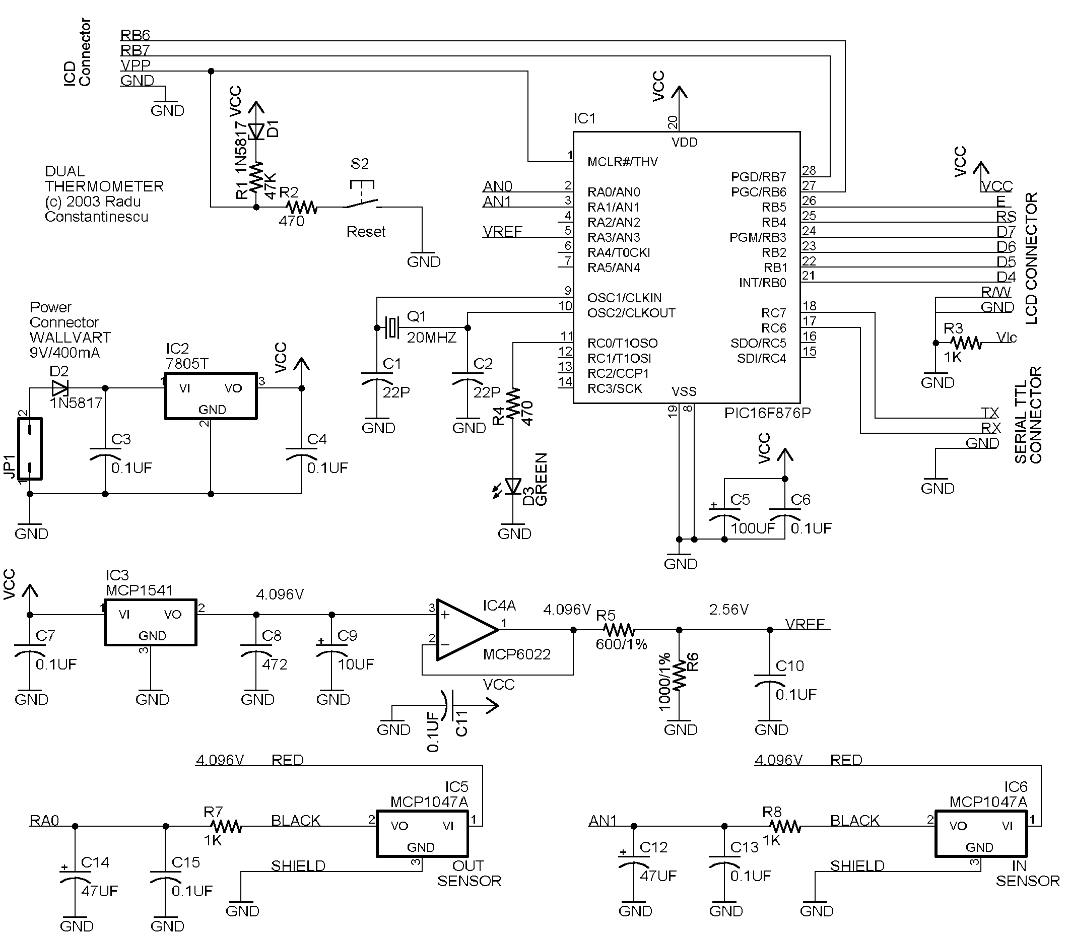
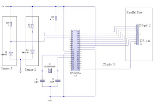
The circuit design incorporates several essential components and methodologies to ensure accurate temperature readings while minimizing noise interference. The PIC16F876 microcontroller acts as the central processing unit, interfacing with the MCP1047A sensors that provide temperature data. The MCP1541 voltage reference ensures stable voltage levels for the A/D conversion process, while the MCP6022 operational amplifier buffers the voltage reference and supplies power to the sensors. The analog output from the temperature sensors is filtered to reduce noise before being converted to digital values by the microcontroller's A/D converter.
The careful layout of the circuit, particularly the star ground configuration and the strategic placement of decoupling capacitors, is critical in maintaining signal integrity. The use of shielded wiring for the sensors enhances protection against electromagnetic interference, particularly important for outdoor applications. The serial communication setup allows for real-time monitoring of temperature data, while the LCD provides immediate visual feedback. The implementation of EEPROM for calibration values demonstrates a robust approach to ensuring accuracy across different sensor placements. Overall, this temperature measurement system exemplifies good engineering practices in circuit design, focusing on reliability, accuracy, and ease of use.This one is using a 16F876 PIC, MCP1047A temperature sensor ( X2 ), MCP1541 voltage reference and MCP6022A opamp. The display is a 2 row HD74780 based 2X16 char, SII L1652BIJ2 but any other display based on HD74780 can be used.
Meantime the thermometer is the favorite of my wife and is showing the outside/inside temperature and was working in the last two months . so it can be considered a good design. The Hardware is quite simple but some important points must be checked in order to keep the noise to a minimum and do not influence the A/D readings. Each IC is using a 0. 1UF capacitor mounted as close as possible to the Vcc/GND pins of the IC. The ground circuit should have the shape of a star with a central point. The Vcc circuit should follow the same pattern where possible. Any kind of loops in the power circuit must be avoided. The temperature sensor used has an analog output, with 500mV at 0C ( zero degree Celsius or centigrade ) and a sensitivity of 10mV/Centigrade.
The output of the sensor is filtered in order to eliminate the noise and applied to the A/D inputs of the integrated 10Bits A/D contained in PIC 16F876. As voltage reference a MCP1541 is used. The typical output voltage is 4. 096V this is buffered with a MCP6022 Rail-to-Rail AO and used to power the temperature sensors. Also a resistive divider is used to obtain 2. 56V as reference voltage for the A/D. For the 2. 56V reference voltage used and 10Bit A/D the temperature in centigrade is simple to compute as T=Reading-200/4.
Two sensors are used - one for Outside temperature and one for Inside temperature. MCP1047A sensor is a small SMD device so it was a little bit difficult to handle it the solution was to mount the sensor on a small piece of PCB, connect a shielded wire to it and seal everything in a piece of heat shrink tube and some silicon. Like this I have obtained two water proof sensors. For the outside sensor I hare replaced a piece of the shielded cable with three thin wires (30AWG) in order to make this wires pass thru the window.
Pins RC6 is the serial output the thermometer will send the temperature readings every second using 9600/N/8/1 format. A MAX232 level converter is necessary in order to feed this info to a RS232 port and any terminal program can be used to display it.
Please see the example with HyperTerminal in the picture. The format is: In this stage the CPU/LCD combination could be tested using the "disptest" supplied assembler file. The display connects directly to the PCB using a header connector. This is a view of the "sandwich" PCB+LCD, the orange wire goes to the sensors, the white connector is the wall wart and the red connector is for the ICD and serial.
Two directives are used if simulate is defined the init routine is skipped - this is useful in order to run the code step by step in MPLAB and debug the conversion routines. If debug is defined then the display will show the A/D readings beside the converted values this is useful to check the sensors and compute the calibration values.
The startup code initialize the used ports an read the two correction values from EEPROM. These values can be used to correct the sensor "shift" once the thermometer is working both sensors can be placed in the same room and some correction values <>0 programmed in the EEPROM in order to get the same readings from both sensors. The main loop read the sensors, convert the values in Fahrenheit and Centigrade, write the values to the LCD and the serial port, flip the LED and the repeat itself.
The A/D is used in sleep mode to minimize the conversion noise and make the last bit stable, then the temperature in Fahrenheit is computed as TF=Reading*0. 45-58 in order to use only positive numbers in the multiplication routine and the temperature in Centigrade is computed as TC=Reading-200/4.
🔗 External reference
Related Circuits
The circuit comprises a Microchip PIC 16F84 microcontroller and an LCD text module. The author claims that this counter can measure frequencies ranging from 400 Hz to 50 MHz. A faster version, the 20 MHz PIC 16F84A-20I/P, was utilized,...
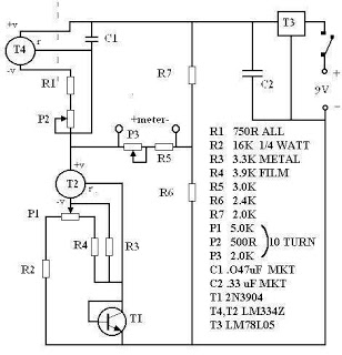
There are many digital thermometers with ±1°C displays, but their accuracy is approximately ±1°C and they cannot be calibrated. A thermometer circuit was created using components available at a local electronics hobby shop, providing an educational experience. For a...
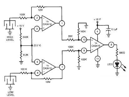
This liquid level sensor electronic circuit diagram utilizes a common CA3410 operational amplifier integrated circuit (IC). The sensor employs two plate sensors (or probes), one designated for detecting high liquid levels and the other for low liquid levels. If...
The dual-channel thermometer is a simple project based on a PIC microcontroller with ADC capabilities. It is an inexpensive thermometer that utilizes low-cost components and does not require high-sensitivity or expensive sensors. Instead, it employs a simple silicon diode...
This program uses an 8 bit DAC along with a 16F84 PIC microcontroller to generate a keyed sine wave. The 16F84 uses an RC clock which can be varied (with a suitable potentiometer) to allow a variable frequency control...
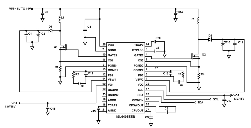
The ISL6405 is a highly integrated voltage regulator and interface integrated circuit (IC) designed to supply power and control signals from advanced satellite set-top box (STB) modules to the low noise blocks (LNBs) of two antenna ports. This device...
Warning: include(partials/cookie-banner.php): Failed to open stream: Permission denied in /var/www/html/nextgr/view-circuit.php on line 713
Warning: include(): Failed opening 'partials/cookie-banner.php' for inclusion (include_path='.:/usr/share/php') in /var/www/html/nextgr/view-circuit.php on line 713