
LM1035 36 application circuit
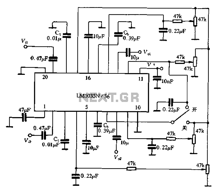
The loudness compensation circuit is designed to enhance audio playback by boosting lower frequency sounds, which can be particularly beneficial when listening at lower volumes. The circuit operates based on a straightforward switching mechanism that connects different pins depending on the desired state of the loudness compensation feature.
In the OFF state, the connection between pins 7 and 17 ensures that the circuit does not engage the loudness compensation, maintaining a flat frequency response. The 4V at pin V7-5 indicates that the circuit is effectively bypassed, allowing for standard audio output without any alteration to the bass frequencies.
When the loudness control is activated (ON position), the connection shifts to pins 7 and 12, which engages the loudness compensation function. This activation allows the circuit to process the audio signal differently, enhancing the bass frequencies to provide a richer sound experience. The adjustment of capacitors Ct and Cb is crucial for tailoring the loudness characteristics to the specific requirements of the audio system, allowing for fine-tuning based on user preference or room acoustics.
Additionally, the external treble control capacitor connected to pins 3 and 18 provides flexibility in managing high-frequency response, enabling users to adjust treble levels independently of the loudness compensation. Similarly, the external bass control capacitor at pin 615 allows for further customization of low-frequency response, ensuring that the sound output can be optimized for various listening environments or personal preferences.
Overall, this circuit configuration provides a versatile solution for enhancing audio playback, allowing for both loudness compensation and independent control over treble and bass frequencies.7 feet for loudness compensation control terminal, the foot plus the DC control voltage can be composed of simple loudness compensation, was obtained additional high bass boost . When loudness control switch in the off position (Figure 4-22), 7 feet and 17 feet in contact, then V7-5 4V, loudness compensation does not work; When the control switch in the ON position 7 feet and 12 feet in contact, the availability of loudness compensation. Change Ct or Cb capacity or changing the voltage of 7 feet, can be adjusted loudness compensation characteristics.
3,18 feet are two-channel external treble control capacitor C external terminal; 615 feet are two-channel external bass control capacitor CI) external end.
Related Circuits

This circuit is simple and inexpensive, which is its primary advantage. Although the output power is not high, the audio quality is good due to the TDA1910's low noise characteristics. This circuit is suitable for use as a student...
Circuit Magic is an electrical circuits simulation program specifically designed for students teaching basics electronics, electrical laws & circuit theory. Unlike many electronic circuit analyzers, Circuit Magic can analyze circuits like a man. Circuits are simulated step by step,...
The circuit with the original m rJ bamboo is designed similarly. It includes a secondary disk that functions as a floodlight. A grass-flow filter is incorporated for a light input. An electric connection is established with a door button...
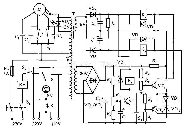
The circuit depicted in the figure includes an automatic voltage regulator (T) that maintains a constant output by utilizing a servo motor. The circuit features transistors VT1 and VT2 (3DK9), with a capacitance range of C (65 ~ 85)....
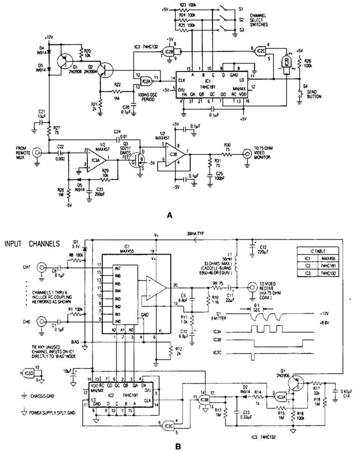
In the video system shown in Figs. A and R, a single coaxial cable transmits power to a remote location, selects one of eight video channels, and returns the chosen signal. This system can select from multiple remote surveillance...

The YSS247 has several characteristics, including fewer external components compared to similar products. Unlike the SRS5250S, the YSS247 utilizes a single potentiometer to adjust the surround effect. The circuit allows for switching or turning the tone control to modify...