
LM1875 DC current of the negative feedback circuit BTL
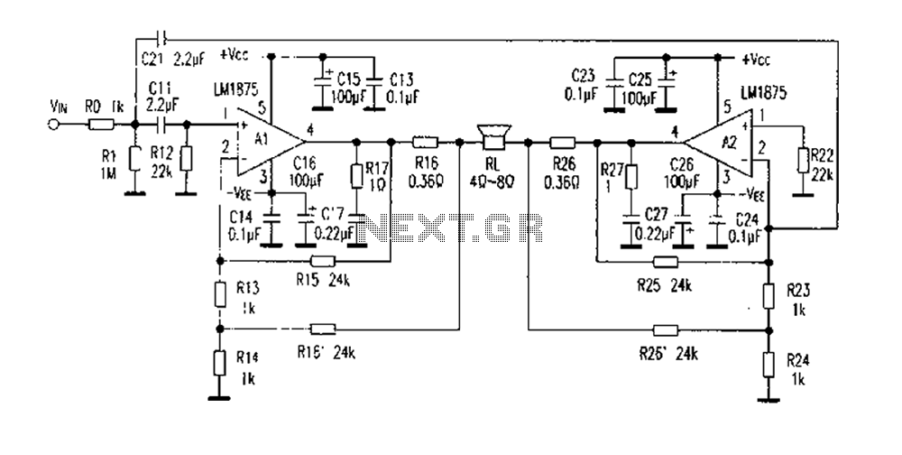
The DC current negative feedback BTL (Bridge-Tied Load) circuit is designed to enhance audio performance by eliminating certain capacitors typically found in standard BTL configurations. By removing capacitors C12 and C22, the circuit achieves improved DC characteristics, which is critical for audio fidelity. The configuration employs sampling resistors R16 and R26 to monitor the output current, while resistors R15, R16, R25, and R26 are utilized to provide feedback signals to the operational amplifiers A1 and A2, ensuring accurate amplification of the audio signal.
The gain of the amplifier is determined by the values of resistors R13, R14, R15, and R16, which can be adjusted to meet specific performance requirements. The circuit has been tested under various conditions, confirming its stability even when subjected to high volume levels. Notably, the design prevents self-excitation when the input terminal is disconnected or reconnected, which is a common issue in less robust audio circuits.
Capacitor C11 plays a pivotal role in the overall sound quality of the output. Its removal has been found to result in a notable enhancement of the audio clarity, particularly in the treble frequencies, while also improving the bass response. This indicates that the circuit design allows for fine-tuning of audio characteristics based on component selection.
The DC current negative feedback BTL circuit effectively inherits the beneficial properties of the direct current negative feedback OCL (Output Capacitor-Less) circuit, which is known for its low distortion and high fidelity. The output power capability is significantly increased, reaching over 60 watts, which is advantageous for driving speakers without introducing hum or static noise, particularly in switching scenarios. The LM1875 operational amplifier is identified as an ideal component for optimizing this circuit design, providing a reliable and efficient solution for high-quality audio amplification.DC current of negative feedback BTL circuit shown in Figure 2, the abolition of the standard BTL circuit C12, C22, the circuit of the DC; resistor R16 and R26 are sampling resi stor, current feedback signal by R15, R16, R25, R26, respectively, into the amplifier A1, the inverting input of A2, R13, R14, R15, R16 resistance determines the amplifier gain. Experiment with the circuit in Figure 2, the power-off anyway with the input signal, the output of the DC output has not, and there is no static output noise, only a slight boot horn A pair of sound, no noise when turned off the speaker can be heard.
Experiments found that such input circuit is very stable, even in high volume, or static input terminal unplugging and plugging in the circuit will not be self-excited. Capacitor C11 a great impact on the sound quality, remove this capacitor, the eyes immediately light up, become clear and delicate treble, bass and elastic strength.
DC of current negative feedback circuit BTL inherits the advantages of direct current negative feedback circuit OCL sound quality, distortion is further reduced, the output power is increased to three times the original, up to 60 watts or more, to overcome its switch speaker has an impact there hum sound and disadvantages of static, the LM1875 is ideal circuit optimization.
Related Circuits
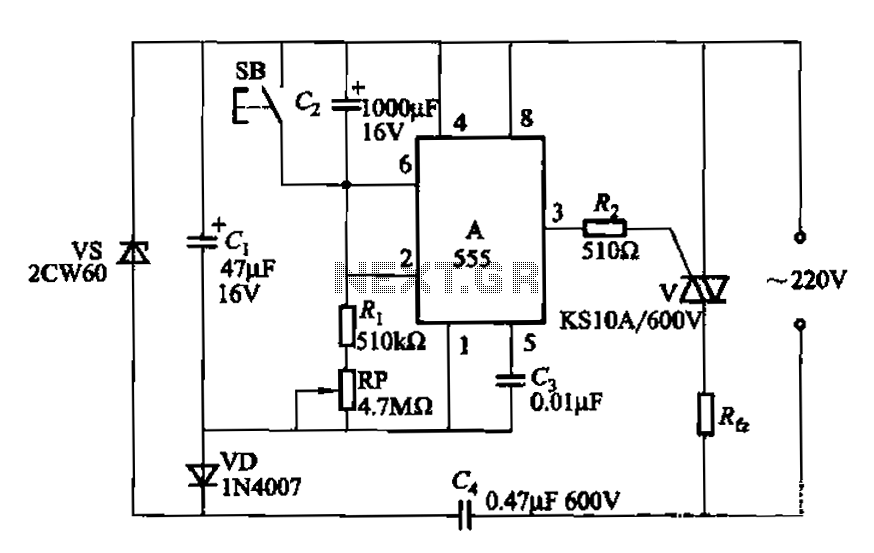
The circuit utilizes a 555 Integrated Circuit (IC) configured as a delay circuit. It transitions from a low to a high state after a button (SB) is pressed, initiating a delay before the output terminal goes high. The output...
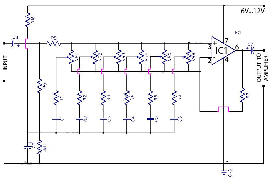
This circuit is a six-band graphic equalizer that allows modification of sound across low, mid, and high frequencies using an IC 741 operational amplifier. It enables management and mixing of frequencies and tones as desired. The audible frequency spectrum...
The BC547 transistor has a maximum operating current of 100 mA and a maximum voltage rating of 65 volts. When oriented with the label facing the viewer, the three terminals from left to right are collector, base, and emitter....
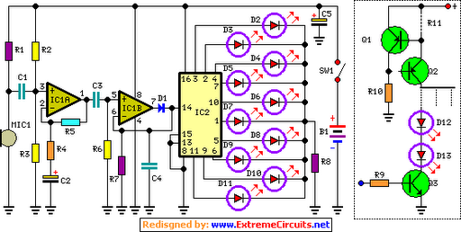
The basic circuit illuminates up to ten LEDs in sequence, following the rhythm of music or speech picked up by a small microphone. The expanded version can drive up to ten strips, each formed by up to five LEDs,...
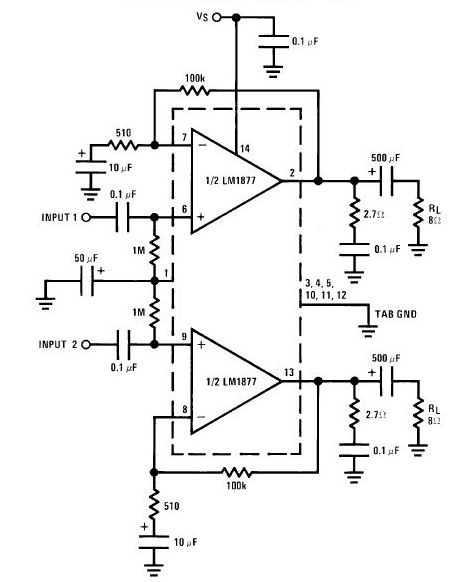
The LA4440 is a dual-channel audio power amplifier integrated circuit (IC) designed for stereo and bridge amplifier applications. In dual mode, it provides significant audio amplification for various audio systems. The LA4440 audio power amplifier is engineered to deliver high-quality...
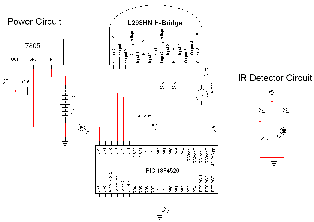
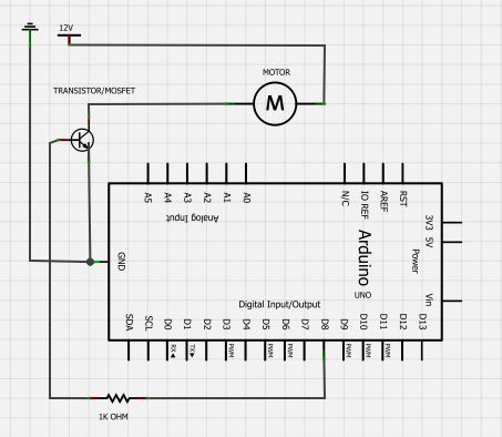
The simple motor optical encoder circuit is not particularly difficult; however, it requires careful verification to ensure all connections are correct before initial operation. The primary components utilized in the circuit include the 7805 voltage regulator, the PIC18F4520 microcontroller,...
Warning: include(partials/cookie-banner.php): Failed to open stream: Permission denied in /var/www/html/nextgr/view-circuit.php on line 713
Warning: include(): Failed opening 'partials/cookie-banner.php' for inclusion (include_path='.:/usr/share/php') in /var/www/html/nextgr/view-circuit.php on line 713