
Simple Motor Optical Encoder Circuit
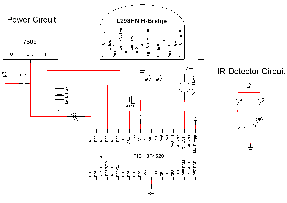
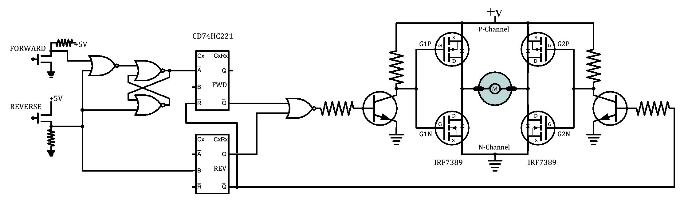
The circuit design is centered around the integration of these components to achieve precise motor control and reliable feedback from the optical encoder. The 7805 voltage regulator plays a crucial role in ensuring that the microcontroller and IR detector receive stable power, which is essential for the consistent operation of the entire system. The PIC18F4520 microcontroller is programmed to generate pulse-width modulation (PWM) signals that control the speed and direction of the motor. The PWM signals are critical as they allow for smooth acceleration and deceleration, enhancing the overall performance of the motor.
The optical encoder setup consists of an IR LED and an IR phototransistor, arranged such that the LED illuminates the surface of the encoder disk. As the disk rotates, it reflects light back to the phototransistor, which detects the changes in light intensity corresponding to the black and white patterns on the disk. The output voltage from the phototransistor is fed back to the PIC microcontroller, where it is processed to determine the position and speed of the motor.
The L298HN motor driver is designed to handle high current loads and is capable of driving bipolar stepper motors and DC motors. By connecting the enable pin to a high logic level, the driver is kept active, reducing the complexity of the control logic required in the microcontroller code. The integration of a 12V battery supply ensures that the motor receives sufficient voltage to operate effectively, while the separate +5V supply for digital components maintains the integrity of the control signals.
In summary, this motor optical encoder circuit effectively combines power regulation, motor control, and feedback mechanisms to create a robust system for precise motion control applications. Proper assembly and verification of connections are essential to ensure the reliable operation of the circuit upon initial power-up.The simple motor optical encoder circuit is not terribly difficult however it will take some double checking to make sure you have everything hooked up properly before working the first time. The main devices used in the circuit are the 7805, 18F4520 and L298HN. This is a basic +5v power regulator circuit for the digital signals/components. Thi s +5v is also fed to the IR detector circuit. A 7805 device is used for regulating. This a very common +5v regulator and can be found at nearly any manufacturer. The PIC has two man chores for this circuit. (1) It is controlling the motor through RC1 & RC2 which are outputing PWM signals. RC1 outputs a certain PWM signal and RC2 outputs the exact inverse. (2) The PIC is also getting data from the IR detector circuit. Namely the voltage at the output. The change in voltage at the point will tell us whether the optical encoder sees black or white. This is as simple as it gets for IR detector circuits. We use two resistors and the two IR components with a power supply. The IR LED shines onto the encoder paper we will build and the IR detector gets the reflected signal. The L298 will receive all its commands from the PIC microcontroller at input 3 and input 4. I chose to make Enable B always enabled just so there would be less programming in the PIC. The motor controller is also directly hooked up to the 12v battery supply voltage as well as the +5v supply for the digital signals.
🔗 External reference
Related Circuits
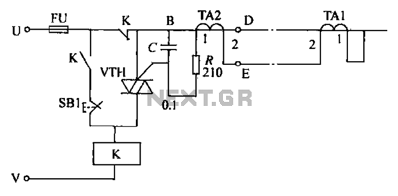
The circuit's current exceeds the load carried by the rated current meter, prompting the user to immediately cut off the power supply to address the overload. Pressing the reset button restores power, making the system simple, convenient, and practical....
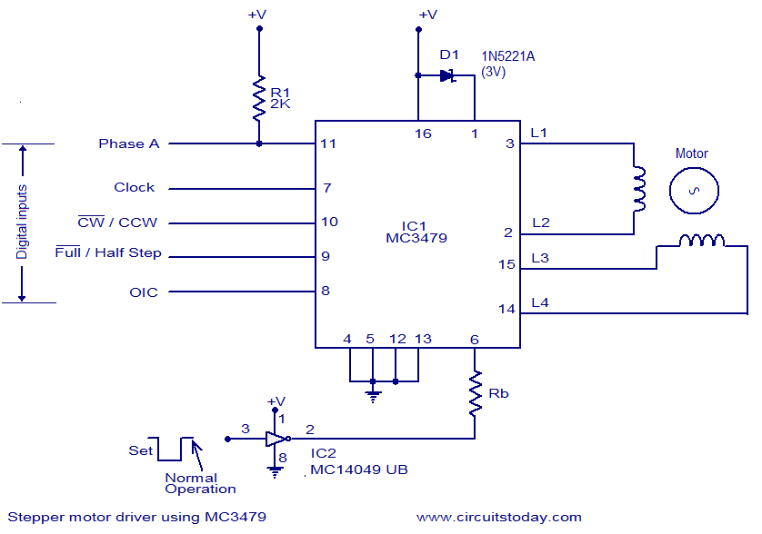
The circuit diagram presented is for a stepper motor driver utilizing the MC3479 integrated circuit from Motorola. The MC3479 is specifically engineered for driving a two-phase stepper motor in bipolar mode and is available in both standard DIP and...

This circuit for a laser door alarm operates on the principle of laser beam interruption. A low-cost laser pointer serves as the light source. When an object disrupts the laser beam, an alarm is triggered for a few seconds....
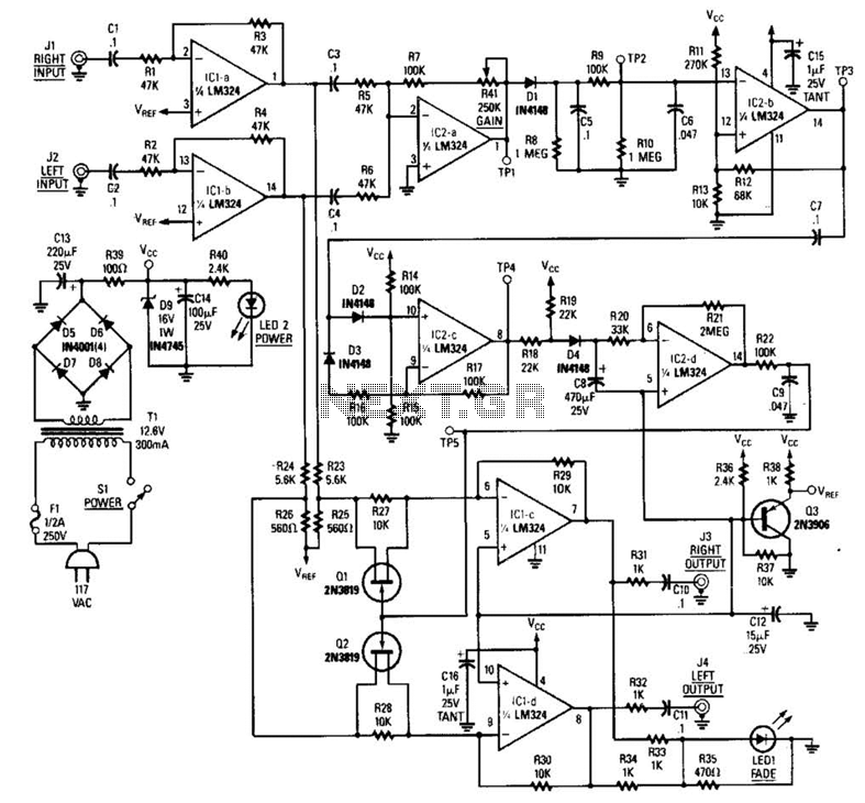
The LR inputs are summed, processed, and then drive a comparator. This comparator detects levels and generates transitions when audio inputs exceed or fall below predetermined thresholds. The frequency of these transitions, which correspond to rapid volume changes, is...
A brief background is provided, indicating a basic understanding of electronics, including knowledge of component functions and schematic reading, but lacking further expertise. The circuit in question appears to involve fundamental electronic components, which may include resistors, capacitors, diodes, transistors,...
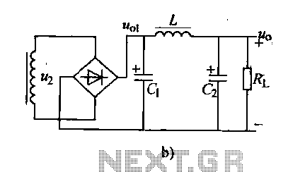
Analyzing the filter capacitance or inductance shows that the filtered DC output remains somewhat volatile. In situations requiring a smoother DC output, a duplex filter can be employed. The LC filter, which consists of a capacitor and inductor, is...
Warning: include(partials/cookie-banner.php): Failed to open stream: Permission denied in /var/www/html/nextgr/view-circuit.php on line 713
Warning: include(): Failed opening 'partials/cookie-banner.php' for inclusion (include_path='.:/usr/share/php') in /var/www/html/nextgr/view-circuit.php on line 713