
LM1889 IC For Simple TV Transmitter

The circuit utilizes the LM1889 IC, which is designed for television applications, particularly for generating the necessary video signals for transmission. The IC integrates various functions required for the modulation of chrominance and luminance signals, enabling the generation of a composite video output suitable for RF transmission.
In this configuration, the input video signal is processed through the LM1889, which modulates the chroma signal using quadrature techniques. This modulation is essential for maintaining the quality of the color signal in the transmitted output. The RF section of the circuit typically includes a power amplifier and an oscillator, which are responsible for converting the modulated video signal into a radio frequency suitable for broadcasting.
The circuit may also include additional components such as resistors, capacitors, and inductors to filter and stabilize the output signal, ensuring that it meets the necessary specifications for transmission. Proper layout and component selection are critical to minimize interference and maximize the range and clarity of the transmitted signal.
Overall, this simple TV transmitter circuit provides a foundational understanding of how video signals can be transmitted over radio frequencies, utilizing the capabilities of the LM1889 IC for effective modulation.The following circuit shows about simple TV Transmitter Circuit Diagram. This circuit based on the LM1889 IC. Features: quadrature chroma modulators and RF .. 🔗 External reference
Related Circuits
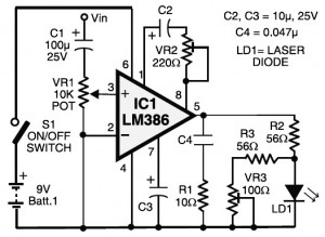
Laser communication system circuit diagram. The circuit module consists of a transmitter and a receiver that utilize the IC LM386. It is powered by a 9V battery. The laser communication system is designed to facilitate wireless data transmission using modulated...
This house FM transmitter for your stereo or any other amplifier provides a strong signal strength up to a distance of 500 meters with a power output of about. This FM transmitter is designed to enhance audio transmission capabilities for...
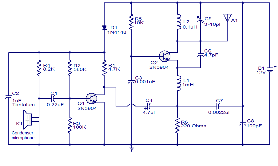
The FM transmitter circuit presented is both stable and simple. With an adaptive antenna, it can achieve a transmission range of approximately 200 meters. This transmitter was developed this year and has yielded positive results. The circuit operates using...
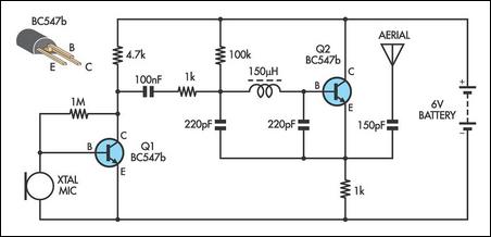
This AM transmitter is notably simple to construct due to its design, which features a non-tapped inductor with a single winding. The inductor is not custom-wound, as it can be sourced from readily available RF chokes, such as the...

This TV transmitter transmits audio and video signals from camcorders, DVD players, VHS players, satellite systems, video games, etc., broadcasting them on a channel free from the VHF strip. These signals can be radiated using a common antenna and...
The transmitter for the wireless headphones is built around a CD4046 CMOS phase-locked loop, coupled with a driver transistor, and a pair of infrared LEDs. More: Although the CD4046 is comprised of two phase comparators, a voltage-controlled oscillator (or...
Warning: include(partials/cookie-banner.php): Failed to open stream: Permission denied in /var/www/html/nextgr/view-circuit.php on line 713
Warning: include(): Failed opening 'partials/cookie-banner.php' for inclusion (include_path='.:/usr/share/php') in /var/www/html/nextgr/view-circuit.php on line 713