
LM2876 amplifier configuration
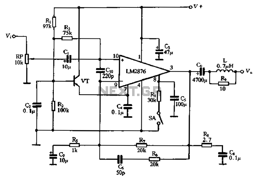
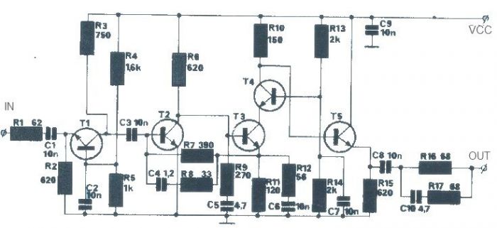
The LM2876 power amplifier circuit is a robust design intended for audio applications, featuring an integrated circuit that simplifies the amplification process while ensuring high fidelity. The use of an external transistor configured as an emitter follower allows for a stable output level, which is essential for maintaining audio quality. This configuration also aids in minimizing distortion and enhancing the linearity of the amplifier's response.
The mute switch (SA) is strategically placed within the circuit to allow for quick disengagement of the amplifier output, providing a means to silence the audio without altering the gain settings. This feature is particularly beneficial in scenarios where immediate silence is required, such as during interruptions or transitions between audio sources.
The potentiometer (RP) serves as a variable resistor, allowing the user to adjust the volume of the audio output. This component is critical for user interaction, providing a simple yet effective means to control sound levels according to the listener's preference.
Capacitor C4 plays a significant role in the overall performance of the amplifier. By connecting it to the AC ground, it acts as a filter that improves the common mode rejection ratio (CMRR). A higher CMRR indicates better performance in rejecting noise that may affect the audio signal, leading to clearer sound reproduction. The choice of a 7-foot capacitance value is specifically aimed at optimizing the frequency response and enhancing the amplifier's ability to handle various audio signals without introducing unwanted artifacts.
In summary, this power amplifier circuit design effectively integrates various components to ensure high-quality audio output while providing user-friendly features such as volume control and a mute function. The careful selection of components and their configuration is crucial for achieving optimal performance in audio applications.A single power amplifier circuit LM2876 crrL constituted. VTf external transistor to form the emitter type to provide neutral level (7 feet) for the LM2876, guaranteed lC relia ble noise suppression circuit and associated circuitry bias. Mute switch button switch SA. Potentiometer RP for the volume control. Capacitor C4 is 7 foot AC ground capacitance, the purpose is to improve the common mode rejection ratio of the amplifier, power amplifier to improve sound quality.
Related Circuits
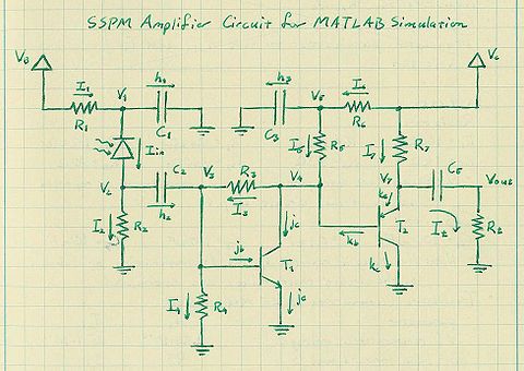
The silicon photomultipliers (SiPM) utilized in the experiment were acquired from Photonique, which also provides analog electronics boards to amplify the signals from the SiPMs. This document addresses the analysis and modeling of the amplifier circuit, along with the...
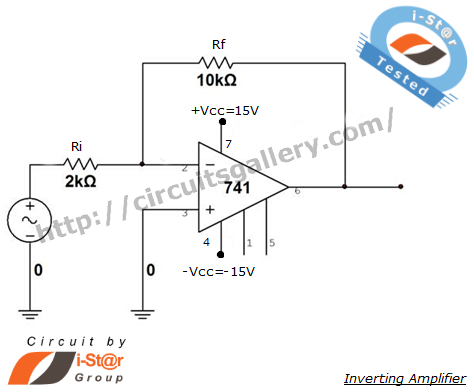
An inverting amplifier is one of the most widely used operational amplifier circuits. The output adjusts in a manner that counteracts changes caused by the input, thereby preventing saturation and ensuring stability. By connecting a resistor from the output...
Integrated circuits (ICs) have largely replaced traditional circuits like this one; however, this circuit is still utilized where the flexibility of a discrete device design is desirable. The components are readily available, and the issue of IC obsolescence is...
The LM317 integrated circuit (IC) is commonly recognized as an adjustable voltage regulator. However, it also has the capability to function as an audio amplifier, specifically in Class A configurations. The LM317 can be utilized in audio amplification applications due...
The T1 transistor must be of the BF200 type (or a similar variant), while the other transistors can be of the BF214 type. To achieve high efficiency, the antenna amplifier should be positioned at a short distance from the...

An audio power amplifier circuit for a 3-watt stereo amplifier using the MAX 7910 IC is explained below. The audio power amplifier circuit utilizing the MAX 7910 IC is designed to deliver a maximum output power of 3 watts per...