
3 W Stereo amplifier using MAX 7910-Audio power amplifier circuit

The audio power amplifier circuit utilizing the MAX 7910 IC is designed to deliver a maximum output power of 3 watts per channel in a stereo configuration. The MAX 7910 is a dual power amplifier IC that is optimized for audio applications, providing high efficiency and low distortion, making it suitable for various audio amplification needs.
The circuit typically consists of the MAX 7910 IC, passive components such as resistors and capacitors, and additional circuitry to handle input and output signals. The input audio signal is fed into the amplifier through a coupling capacitor, which blocks any DC component and allows only the AC audio signal to pass. The gain of the amplifier can be adjusted by selecting appropriate feedback resistors, ensuring that the output level matches the requirements of the connected speakers.
The power supply for the circuit should provide a regulated voltage typically between 5V to 15V, depending on the specific application and desired output characteristics. Bypass capacitors are recommended near the power supply pins of the IC to filter out any noise and ensure stable operation.
The output stage of the MAX 7910 is designed to drive low-impedance loads, making it ideal for connecting directly to speakers. A heat sink may be required to dissipate heat generated during operation, especially at higher output levels.
Overall, the design of this audio power amplifier circuit is aimed at achieving a compact, efficient, and high-quality audio amplification solution suitable for various consumer electronics applications.An audio power amplifier circuit for 3 watts stereo amplifier using max 7910 IC is explained below.. 🔗 External reference
Related Circuits
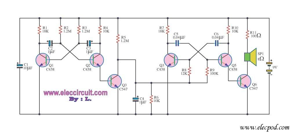
This circuit produces a siren-like sound similar to that of ambulance sirens. Unlike traditional ambulance siren circuits that typically use an IC 555, this design employs transistors, making it more economical and easier to customize. The operation of the...
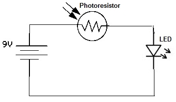
A simple photoresistor circuit will be constructed to demonstrate the operation of a photoresistor, which activates the circuit in the presence of light and deactivates it in darkness. This circuit connects a photoresistor to an LED. When the photoresistor...
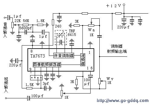
The circuit design philosophy allows for debugging without any RF instruments. Although its performance may not match that of professional equipment, it should be adequate for hobbyists, with audio-visual transmission effects comparable to general-purpose machines. The transmitter consists of...
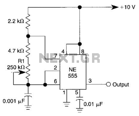
This simple square-wave generator produces a variable frequency output ranging from 2800 Hz to 80 kHz, as indicated by the specified values. The frequency can be adjusted using potentiometer R1. The square-wave generator circuit typically employs a combination of resistors,...
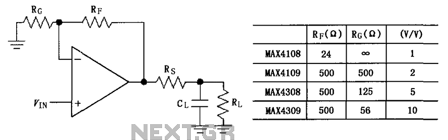
The circuit depicted in the figure employs the MAX4108/4109/4308/4309 operational amplifiers with a capacitive load driving circuit isolation resistor (Rs). While the MAX4108/4109/4308/4309 exhibits excellent AC characteristics, it is not optimized for driving high-load electrical resistances. A significant reactive...
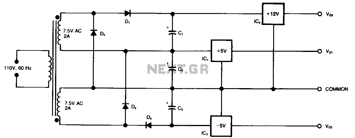
This circuit generates three supply voltages using a minimal number of components. Diodes D2 and D3 perform full-wave rectification, alternately charging capacitor C2 during both halves of the AC cycle. Meanwhile, diode D1 in conjunction with capacitor C1, and...
Warning: include(partials/cookie-banner.php): Failed to open stream: Permission denied in /var/www/html/nextgr/view-circuit.php on line 713
Warning: include(): Failed opening 'partials/cookie-banner.php' for inclusion (include_path='.:/usr/share/php') in /var/www/html/nextgr/view-circuit.php on line 713