
LM317 Low-Cost 3A Switching Regulator
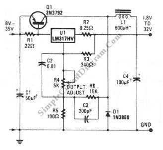
The switching voltage regulator circuit operates by converting a higher input voltage to a lower output voltage with minimal energy loss, making it suitable for applications where efficiency is crucial. The core components typically include an inductor, a switch (usually a transistor), a diode, and output capacitors.
In the circuit, the switch alternates between the on and off states, controlling the energy transferred to the inductor. When the switch is closed, current flows through the inductor, storing energy in the form of a magnetic field. When the switch opens, the inductor releases its stored energy through the diode to the output load. This process allows for efficient voltage regulation and minimizes heat generation compared to linear regulators.
The output voltage can be adjusted using feedback mechanisms that monitor the output voltage and compare it to a reference voltage. This feedback loop ensures that the output voltage remains stable despite variations in load current or input voltage. Additional components such as capacitors at the input and output help filter voltage ripples, ensuring a smooth and stable output.
Overall, this switching voltage regulator circuit is ideal for applications requiring efficient power management, such as battery-operated devices, power supplies for microcontrollers, and other electronic systems where space and energy efficiency are paramount.A switching voltage regulator circuit shown in the schematic diagram here can be a low cost solution for your high efficiency requirement electronic circuit.. 🔗 External reference
Related Circuits
The following are current regulator circuits that can be used to drive light emitting diodes. As always, take time to do some testing before attempting to use these circuits in actual applications. Current regulator circuits are essential for controlling the...
This universal battery charger utilizes the LM317 voltage regulator and features an adjustable output voltage along with a constant-current charging circuit, making it suitable for charging most NiCad batteries and various other battery types. The LM317 universal battery charger...
Self-switching power supply. One of the main features of the regulated power supply circuit being presented is that, although a fixed-voltage regulator LM7805 is used in the circuit, its. The self-switching power supply circuit utilizes the LM7805 voltage regulator to...
The circuit in Fig 1 provides both 3.3V and 5V power to transitional circuits that utilize both newer 3.3V devices and older 5V devices. Additionally, due to the regulator... The circuit illustrated in Fig 1 is designed to accommodate the...
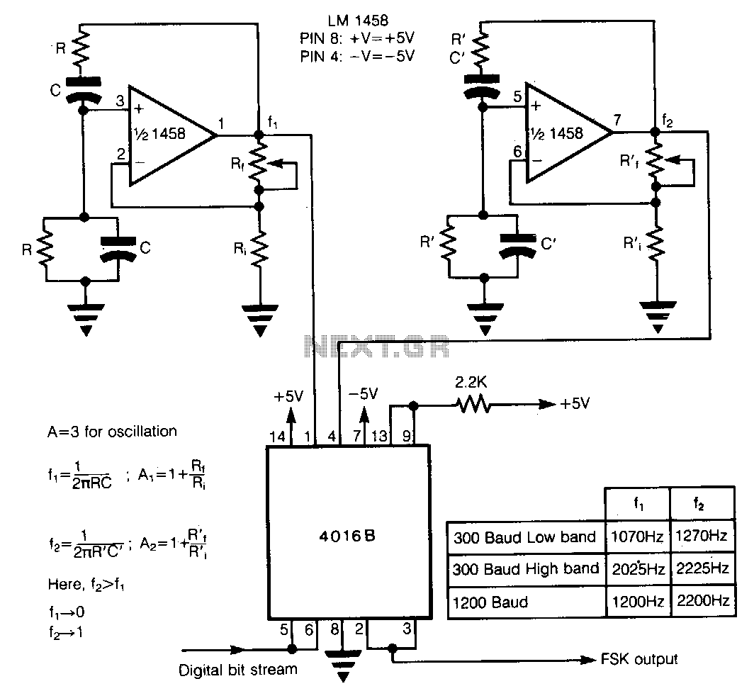
In Frequency Shift Keying (FSK), two distinct frequencies are utilized to represent the binary digits 0 and 1. The core of the circuit comprises two Wien-bridge oscillators constructed with a dual operational amplifier LM1458, each generating one of the...
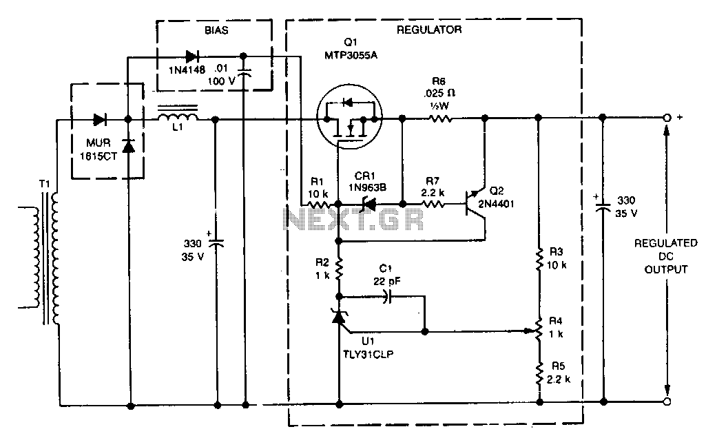
This linear post regulator provides 12 V at 3 A. It utilizes the TL431 reference (U1), which, without additional amplification, drives the gate of the TMOS MTP3055A (Q1) series pass regulator. A bias voltage is applied through resistor R1...