
Dual Regulator Handles Two Input Voltages
The circuit illustrated in Fig 1 is designed to accommodate the power requirements of mixed-voltage systems, supplying both 3.3V and 5V outputs. This dual-voltage capability is essential for integrating newer 3.3V logic devices alongside legacy 5V components, thus facilitating a smooth transition during upgrades or system enhancements.
The circuit typically employs a voltage regulator capable of stepping down a higher input voltage, such as 12V or 9V, to the required output levels. A linear voltage regulator, such as the LM317 for adjustable outputs or the LM7805 for fixed 5V output, can be utilized for this purpose. For the 3.3V output, a low-dropout (LDO) regulator is preferred to minimize power loss and heat generation, especially when the input voltage is close to the desired output voltage.
Input capacitors are recommended at the input of each regulator to stabilize the voltage and filter out noise, while output capacitors help maintain voltage stability during load changes. It is also advisable to include bypass capacitors close to the power pins of the devices being powered to ensure clean power delivery and reduce the effects of electromagnetic interference (EMI).
In addition to the regulators, the circuit may include protection features such as fuses or resettable polyfuses to prevent damage from overcurrent conditions. Furthermore, the design should incorporate adequate heat sinking for the regulators, particularly if the load current is substantial, to ensure reliable operation without thermal shutdown.
Overall, this circuit design effectively bridges the voltage gap between modern and legacy devices, ensuring compatibility and reliable performance in mixed-voltage environments.The circuit in Fig 1 supplies both 3.3 and 5V to transitional circuits that employ both the new 3.3V and older 5V devices. Additionally, because the regul.. 🔗 External reference
Related Circuits
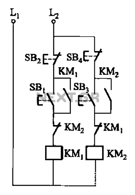
A, B, and two electric motors allow simultaneous operation through interlock control. The two motors can be connected in series with each other using normally closed contacts in the respective coil circuit. The circuit design facilitates the interlocking operation of...
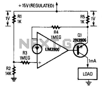
This fixed 1-mA current source delivers a constant current to a load connected between Q1's collector and ground. The load can range from 0 to 14 ohms. The circuit is powered by a regulated 15-V supply, and the R1/R2...
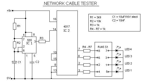
This is a multifunction RJ45 network cable tester designed for testing network cables (RJ45) and telephone cables (RJ11). It is cost-effective and user-friendly. The tester determines whether a network cable is a crossover or straight type by illuminating a...
This is a 28VDC to 5VDC switching converter circuit. As a switch-mode voltage regulator, this circuit provides higher efficiency than linear regulator types. The 28VDC to 5VDC switching converter circuit operates by converting a higher voltage direct current (DC) input...
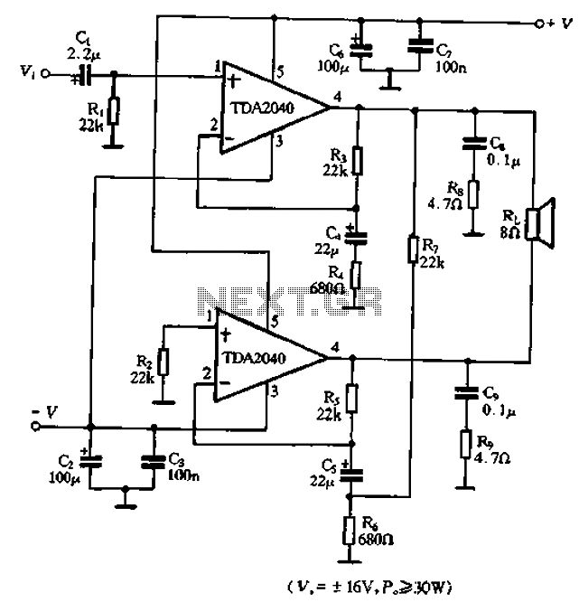
The TDA2040 is a power audio amplifier with a wider operating voltage range compared to the TDA2030, ranging from 4V to 20V. It can deliver an output power of 18W at a load of 4 ohms when supplied with...
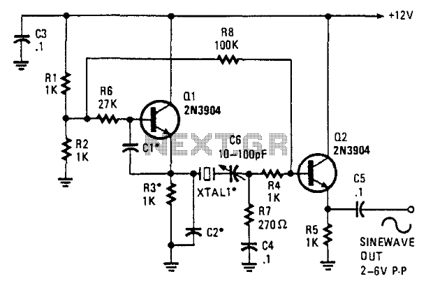
This oscillator employs two transistors and operates the crystal in its fundamental mode. Capacitors CT and C2 should be approximately 2,700 pF for 1 MHz, 680 pF for 5 MHz, and 330 pF for 10 MHz. A capacitance of...