
Lm317 Regulator Sensing

The circuit utilizes an optocoupler to achieve electrical isolation between the control and load sides of a power supply system, particularly when interfacing with a 3-terminal voltage regulator like the LM317. The optocoupler operates by allowing a small input current to control a larger output current, effectively providing feedback on the load conditions without direct electrical connection.
In this configuration, resistor Rl is critical as it establishes a current of 5 mA flowing through the input side of the optocoupler. This current is necessary for the optocoupler's LED to emit light, which in turn activates the phototransistor on the output side. The selection of Rl is based on the desired current through the optocoupler and the forward voltage drop of the LED within it.
Resistor R3 is also an essential component, as it is used to set the output voltage across the load to 12 V. This resistor is typically adjusted to ensure that the voltage regulation remains stable under varying load conditions. The combination of Rl and R3 allows for precise control and feedback, ensuring that the LM317 regulator can maintain the desired output voltage even as the load changes.
The optocoupler's role in this circuit is to provide feedback to the regulator, allowing it to adjust its output in response to changes in load conditions. This is particularly useful in applications where the load may vary significantly, as it helps to maintain consistent voltage levels and improves the overall stability of the power supply system. Proper selection and configuration of the resistors and the optocoupler are essential for achieving optimal performance in this application. The optocoupler (as shown) provides load sensing for a 3-terminal regulator, such as the LM317 series. Rl sets a cu rrent of 5 mA through the optocoupler transistor and R3 is adjusted for 12 V across the load.
Related Circuits
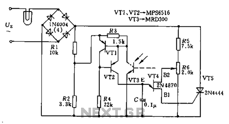
The circuit utilizes a thyristor-based AC automatic voltage regulator to stabilize the brightness of lamp L. A diagonal line connects the thyristor to the T5 bridge. The trigger pulse for the thyristor is generated by a single-junction transistor, VT4....
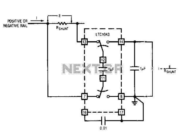
This capability has wide application in battery and solar-powered systems. If the ground-referred voltage output is unloaded by an amplifier, the shunt can operate with very little voltage drop across it, minimizing losses. The LTC1043 can sense current through...
The LM117 series of adjustable 3-terminal positive voltage regulators is capable of supplying in excess of 1.5A over a 1.2V to 37V output range. They are exceptionally easy to use and require only two external resistors to set the...
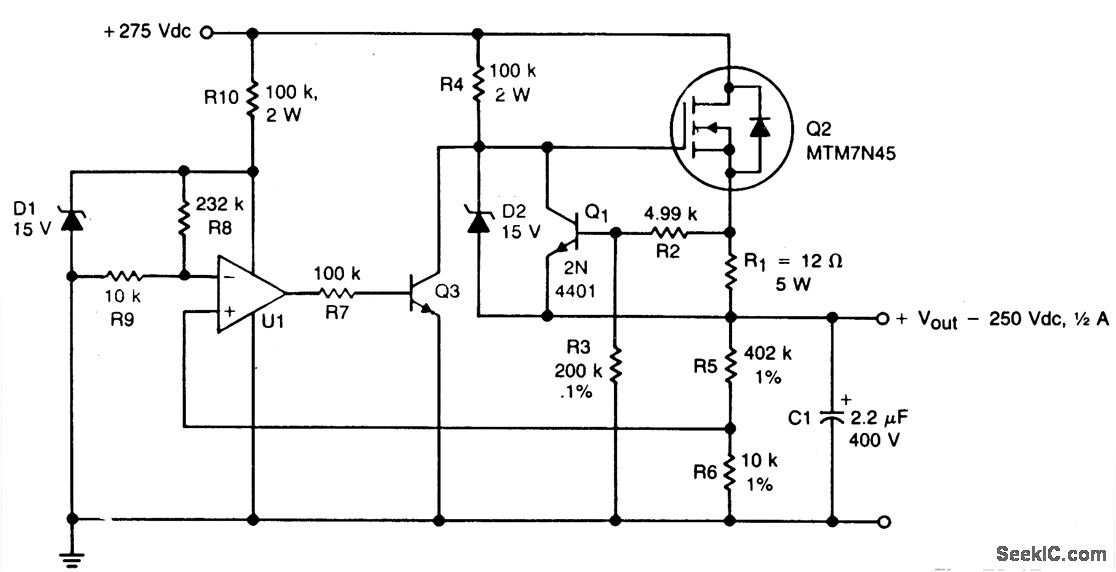
A TMOS MTM7N45 (Q2) functions as a series pass element in a linear high voltage supply that accepts +275 V unregulated input and produces a regulated output of 250 V, incorporating foldback current limiting. A 15 V zener diode,...
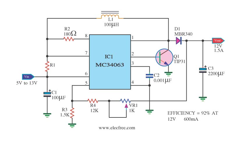
The circuit is a battery-powered voltage regulator that outputs 12V at 1.5A. It accepts an input voltage range from 5V to 13V. The circuit utilizes the MC34063 integrated circuit, making it a straightforward design. The circuit primarily functions as a...
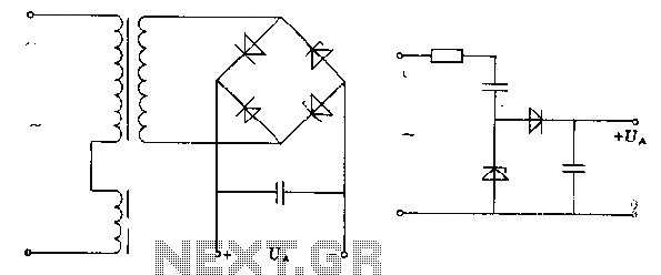
The pre-regulator circuit is connected to a capacitor and a resistor element. The regulator operates in its conducting direction through the input. A capacitor is connected to AC power, and in the blocking direction, it limits the current, allowing...