
Thyristor AC automatic voltage regulator circuit diagram
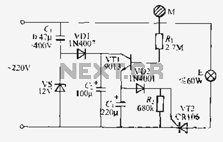
The described circuit is an effective solution for maintaining consistent lamp brightness through the use of a thyristor-based automatic voltage regulator. The thyristor serves as a controlled rectifier that adjusts the amount of power delivered to the lamp based on the feedback from the phototransistor arrangement.
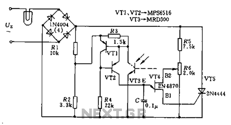
The circuit begins with the AC supply, which is fed into the T5 bridge rectifier. This bridge converts the AC voltage into a pulsating DC voltage suitable for the thyristor's operation. The thyristor, when triggered, allows current to flow through the lamp, and its conduction time is modulated based on the feedback mechanism involving the phototransistors.
The phototransistors (VT1, VT2, VT3) are strategically placed to monitor the light output of the lamp. As the lamp's brightness fluctuates due to changes in load or supply voltage, the phototransistors detect these variations. The change in light intensity results in a corresponding change in their resistance, which affects the voltage at the base of the single-junction transistor (VT4).
The single-junction transistor acts as a control element that generates the trigger pulse for the thyristor. The phase shift of this trigger pulse is crucial; it determines how long the thyristor remains conductive during each AC cycle. By increasing or decreasing the conduction time, the circuit can effectively regulate the average voltage supplied to the lamp.
This feedback loop creates a stable light output, as the system continuously adjusts to maintain the desired brightness. The overall design is efficient and reliable, making it suitable for various applications where consistent lighting is essential. The use of solid-state components like transistors and thyristors enhances durability and reduces maintenance needs compared to mechanical dimming solutions. As shown in the circuit in order to stabilize the lamp brightness L, using thyristor AC automatic voltage regulator circuit. Access to this end a diagonal line from the thyrist or T5 bridge of exchanges. Its trigger pulse is generated by single-junction transistor VT4. Transistor VT1, VT2 and VT3 phototransistor equivalent resistance from the role. When the lamp light power is due to change, the change in resistance of the phototransistor, single-junction transistor control voltage phase also changed, so that the trigger pulse thyristor phase shift, increase or decrease the thyristor conduction time, L on the approximation of the voltage remains constant, the brightness of the lamp is also kept approximately constant, so that the light stability.
Related Circuits
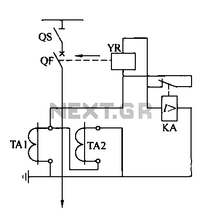
Operating power protection devices can be categorized into two types: DC power supply operation and AC operation. AC operating power is favored due to its lower investment costs, simpler operation, and reliable secondary circuit maintenance, making it widely used...
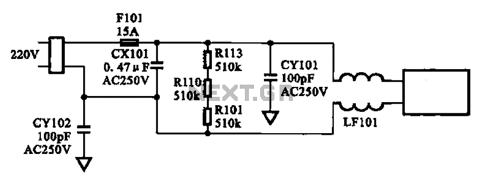
The AC input circuit consists of a fuse (Fl01), a mutual inductance filter (LF101), and filter capacitors (CX101, CY101, CY102), among other components. Its primary function is to filter out noise and pulse interference from the AC circuit, as...
The input stage of this voltmeter circuit utilizes an operational amplifier and diode feedback to create a linear peak value rectifier circuit. A partial pressure isolation through resistors R1 and R2 directs the signal to a dual multi-channel BCD...
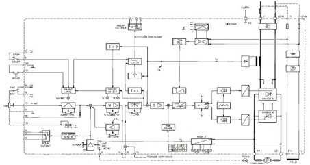
This figure represents the 4Q2 DC Motor Speed Controller Circuit Block Diagram, designed for comprehensive control of conventional shunt-wound and permanent magnet motors with a capacity of up to 75 kW, as specified in the datasheet. This type of...
Utilize the call sheet to touch the electrical threshold M, which causes the E lamp to light up. When the same interval subparagraph is triggered, the lights will automatically turn off. A voltage regulator rectifier circuit is formed using...
This circuit is an enhanced Hartley oscillator, which allows for frequency adjustment within a specified range by altering the base current. The output signal amplitude exceeds 6V when tested with a 6kΩ load resistance, making it suitable for use...
Warning: include(partials/cookie-banner.php): Failed to open stream: Permission denied in /var/www/html/nextgr/view-circuit.php on line 713
Warning: include(): Failed opening 'partials/cookie-banner.php' for inclusion (include_path='.:/usr/share/php') in /var/www/html/nextgr/view-circuit.php on line 713