
lm317 variable power supply circuit project
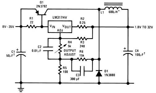
The LM317 is a popular adjustable voltage regulator that is widely used in power supply applications due to its versatility and ease of use. The input voltage range of 8 to 35 volts allows for compatibility with various power sources, making it suitable for a range of applications. The output voltage can be adjusted by changing the resistor values in the feedback network connected to the LM317, enabling a wide range of output voltages from 1.8 volts to 32 volts, suitable for powering different electronic devices.
Capacitors C1 and C4, specified as solid tantalum types, play a crucial role in stabilizing the voltage output and filtering noise. Tantalum capacitors are known for their reliability and stability over a wide temperature range, making them ideal for this application. The use of a 600 µH inductor (L1) in the circuit is essential for smoothing out the output voltage and minimizing ripple, ensuring a stable supply for the connected load. The recommended Arnold A-254168-2 core with 60 turns provides the necessary inductance while maintaining compactness and efficiency in the design.
Overall, this LM317 power supply circuit is a robust solution for providing adjustable voltage outputs, with careful consideration given to component selection for optimal performance and reliability.As you can see in the circuit diagram this LM317 power supply electronic project require few external components. The input voltage required by this electronic project must be between 8 and 35 volt, and will provide a variable output voltage over a wide range, from 1.
8 volts up to 32 volts. C1, C4 capacitors must be a solid tantalum type and L1 coil must have a 600uH inductance. For L1 coil you can use a Arnold A-254168-2 core with 60 turns. 🔗 External reference
Related Circuits
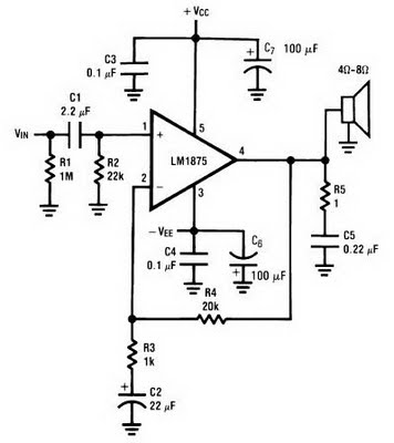
The amplifier circuit can be constructed using the LM1875 power amplifier IC. The LM1875 is a single-chip power amplifier from National Semiconductor. This 20-watt audio amplifier is characterized by low power consumption while delivering high-quality sound suitable for use...

A simple audio watt meter circuit or an audio power or audio level meter circuit with diagram and schematics to measure amplifier audio output power in watts. The audio watt meter circuit is designed to measure the output power of...
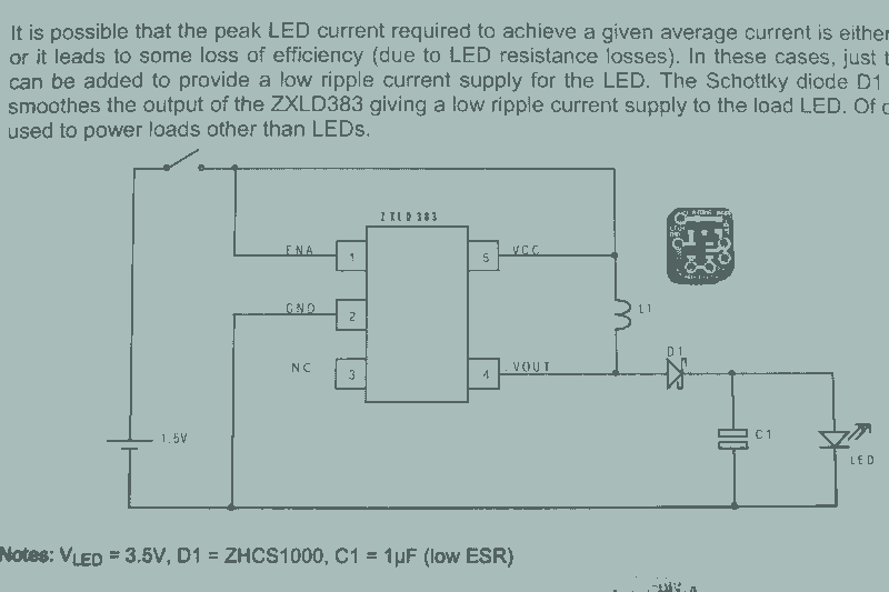
It may seem that due to the numerous flashlight projects undertaken, there is a significant collection of lights. The inductor can be altered to set the current level, but the total current fluctuates with the battery supply, decreasing as...
Many amplifiers have phono inputs for connecting record players to the amplifier. Phono input is designed to take a up to few millivolt signal from phono pickup and amplify it. The amplifier stage does also some equalization based on...
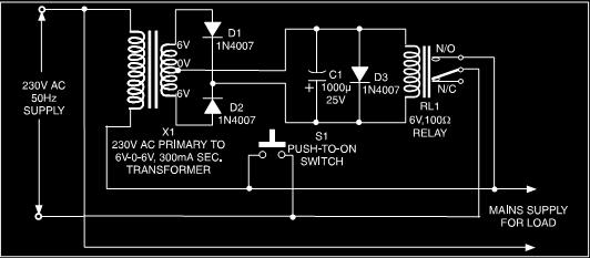
This is a low-cost protection circuit designed to safeguard electrically operated home appliances, such as TVs, DVD players, refrigerators, and other devices, during sudden power outages and the subsequent restoration of mains supply. Appliances like refrigerators and air conditioners...
The circuit operation begins by transmitting stereo surround sound signal quality information through the master volume circuit. This drives the left channel connected to the LCH Model TL072 IC1A and IC1B, which are linked to the right channel (Rch)....