
Line signal to phono adaptor circuit
The described circuit serves as a phono input converter, specifically designed to facilitate the connection of line-level audio sources, typically outputting signals between 0 to 1 volt, to phono inputs that require significantly lower signal levels, typically in the range of 0 to 5 millivolts. This conversion is essential for integrating modern audio equipment with legacy systems, particularly where phono inputs are concerned.
The circuit operates by performing two critical functions: signal level attenuation and inverse RIAA filtering. The attenuation process reduces the nominal input signal of 500 mV down to a nominal output of 2.5 mV, achieving an attenuation of 46 dB. This is accomplished through a resistive divider network that ensures the output signal is compatible with the phono input specifications.
Impedance matching is also a significant feature of this circuit. The input impedance is greater than 10 kΩ, which allows for minimal loading on the source device, while the output impedance is set at 470 ohms, ensuring compatibility with the following stage of amplification in the audio chain.
The inverse RIAA filtering network is integral to the circuit's design, as it compensates for the RIAA equalization typically applied to the audio signal during vinyl mastering. This filtering ensures that the frequency response of the audio playback remains flat, aligning with the original intention of the recording. The circuit's design allows it to accommodate both moving magnet and high-output moving coil cartridges, making it versatile for various audio setups.
The simplicity of the circuit allows for easy construction, enabling users to assemble it with basic soldering skills and minimal components. The circuit can be housed in a compact metal enclosure, with RCA connectors for straightforward integration into existing audio systems.
This design is a simplified adaptation of a previously published circuit, which indicates that while it may not utilize high-precision components, it is still deemed sufficient for general use, especially in applications where cost-effectiveness is a priority. The overall performance, while not on par with more complex designs, remains adequate for many audio applications, particularly for users seeking to repurpose unused phono inputs in modern audio environments.Many amplifiers have phono inputs for connecting record players to the amplifier. Phono input is designed to take a up to few millivolt signal from phono pickup and amplify it. The amplifier stage does also some equalization based on standardized RIAA curve. That RIAA equalization is used in the playback to reduce the high pitch noise and maximize bass dynamics in the phono playback. The audio material which is rocorded to the record has been pre-equalized so that the frequency response of the whole chain from the mixing desk to your speaker will give flat frequency response.
Nowadays phono inputs are largely unused because vinyl record players are getting rare. This circuit is is a simple converter to convert line level signal (0..1 V) to phono input levels (0..5 mV), which makes it possible to use those inputs as an extra line input. This circuit does the level conversion, impedance matching and inverse RIAA filtering. The inverse-RIAA filtering network in this circuit is needed, because all phono inputs have RIAA filter in them.
Input impedance: > 10 kohm Output impedance 470 ohms Nominal input signal level: 500 mV Nominal output signal level: 2.5 mV Attenuation: 46 dB Frequency response: inverse-RIAA Phono input compatibility: moving magnet and high output moving coil type inputs (= compatible with most receivers and integrated amplifiers). The circuit does two functions: signal level attenuation and inverse RIAA filtering. The signal attenuation is needed to convert the 500 mV signal to 2.5 mV signal. The inverse-RIAA filtering is needed to make the frequency response of the system flat (same equalization that is used when music is transferred to vinyl in the studio).
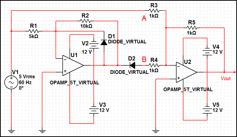
The picture blow shows the frequency response of the ideal inverse-RIAA filter: The picture below shows the circuit diagram of one channel. The other channel (for stereo) is identical. The circuit is so simple that you can easily build it by just soldering the components together and fit them to small metal box with the RCA audio connectors.
This circuit is a simplified version of circuit published in Elektor Electronics (T.Giesberts, Pick-up input becomes line input, Elektor Electronics, December 1995, page 99). The basic circuit idea is same, but my circuit is simpler and it does not use high-precision components.
The performance is not the same, but I think that this circuit build even from 5% components is adequate for many purposes. 🔗 External reference
Related Circuits
This article discusses a fully automatic 6V 4.5AH battery charger circuit that utilizes the LM317T integrated circuit along with a few additional components. The circuit is designed to charge a 6V lead-acid battery. The circuit utilizes the LM317T voltage regulator,...

Fast rise-time high-voltage pulses have various applications, including EMC testing and device characterization. The circuit outlined here is a simple, cost-effective solution designed for the latter purpose. It can generate pulses ranging from 0 to 1000 V with currents...
The optimal operational amplifier circuit used to convert a sine waveform into a rectangular waveform is the Schmitt trigger circuit. The Schmitt trigger circuit is a vital component in signal processing, particularly for converting analog signals into digital signals. It...
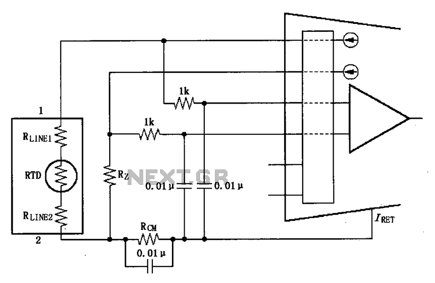
The long wire current loop transmission is susceptible to radio frequency (RF) interference, which can lead to errors in the sensitive input of the XTR108. This interference can occur particularly when the RTD sensor is located at a distance,...
To measure the input impedance of an unknown circuit, first set the signal generator to a current source with a magnitude of 1 amp. A shunt resistor of 100 megohms is also required. This setup is beneficial for measuring...
CocaCola clearly stated that his circuit did not work correctly; the series was only complete when both LEDs were enabled, not otherwise. The circuit in question appears to involve a series configuration of light-emitting diodes (LEDs) that require both components...