
LM324 For Parking Sensor
The LM324 is a quad operational amplifier that is commonly used in various electronic applications, including sensor circuits. In the context of a parking sensor circuit, the LM324 can be utilized to process signals from ultrasonic sensors or similar devices that detect obstacles. The circuit typically consists of the LM324 connected to multiple LEDs that serve as visual indicators for proximity alerts.
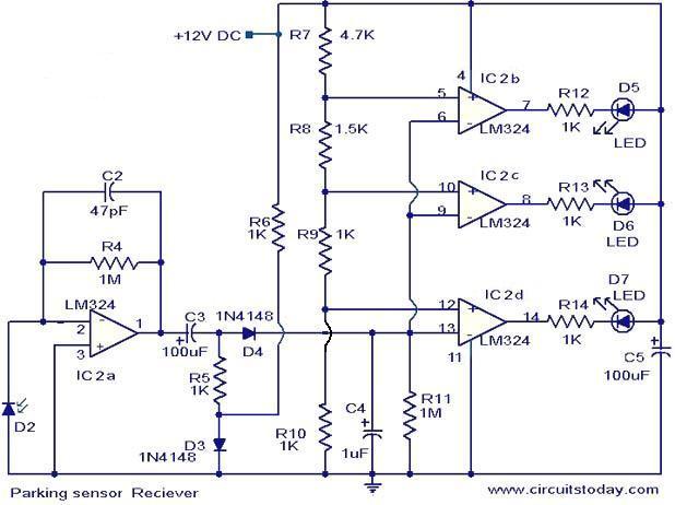
In a standard configuration, the ultrasonic sensor emits sound waves that reflect off nearby objects. The LM324 receives the echo signal and processes it to determine the distance to the obstacle. If the distance exceeds 25 cm, the output from the LM324 does not trigger any of the connected LEDs, indicating that the parking space is clear. Conversely, as the obstacle approaches and the distance decreases, the LM324 can be configured to activate one or more LEDs to provide visual feedback to the driver.
The circuit may include additional components such as resistors and capacitors for signal conditioning and stability. The choice of these components is critical to ensure accurate distance measurement and reliable operation of the sensor. The design may also incorporate a power supply circuit to provide the necessary voltage levels for the LM324 and other components.
Overall, the LM324-based parking sensor circuit serves as an effective solution for enhancing vehicle safety during parking maneuvers by providing timely feedback on nearby obstacles.The following circuit shows about LM324 For Parking Sensor Circuit Diagram. Features: When the obstacle is beyond 25 cm none of the above LEDs .. 🔗 External reference
Related Circuits
It's basically a photovore with a couple tactile sensors. It's rather complex but can give neat behaviors with modifications to the circuit. At this point I don't have any plans to give more information on this circuit so your...

The circuit depicted in the schematic utilizes zero-drift operational amplifiers (LTC1250 and LTC1050) along with a precision instrumentation switched capacitor block (LTC1043). This design achieves exceptional DC accuracy down to microvolt levels. The choice of this method over a...
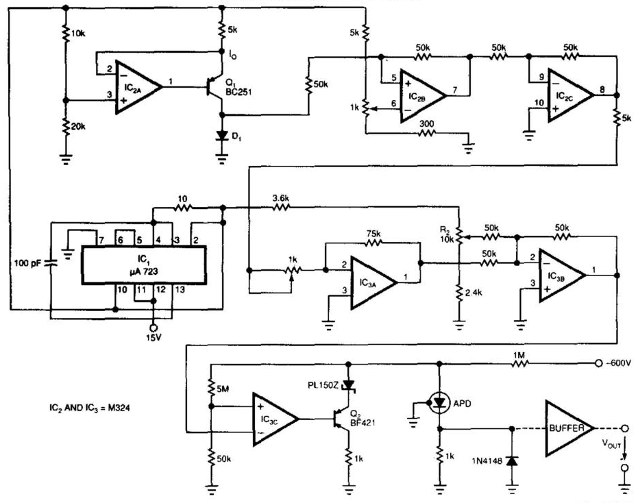
Laser-receiver circuits must bias their avalanche photodiodes (APD) to achieve optimal gain. Unfortunately, an APD's gain depends on the operating temperature. The circuit controls the operating voltage of an APD over a large temperature range to maintain the gain...
This compact water sensor alarm circuit emits a loud warning sound when a humidity sensor detects the presence of water. The circuit utilizes the low-power comparator LM1801 from National Semiconductor. A fixed reference voltage for the integrated circuit is...
Using LM134 and LM10 integrated circuits, a thermometer can be constructed with a sensing range of -55 to 150 °C. The ideal meter for this circuit is a 0-200 µA. The proposed thermometer circuit utilizes the LM134, a current source...
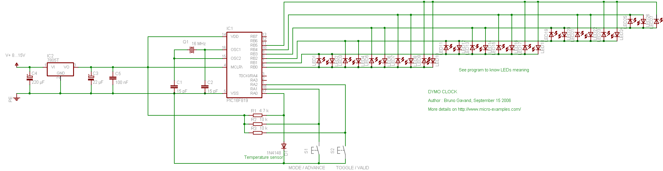
The following circuit illustrates the PIC16F819 Dymoclock Sensor Circuit Diagram. Features include an economical temperature sensor, the use of only LEDs, and the absence of a decoder. The PIC16F819 Dymoclock Sensor Circuit utilizes a PIC16F819 microcontroller, which is a versatile...