
PIC16F819 Dymoclock Sensor
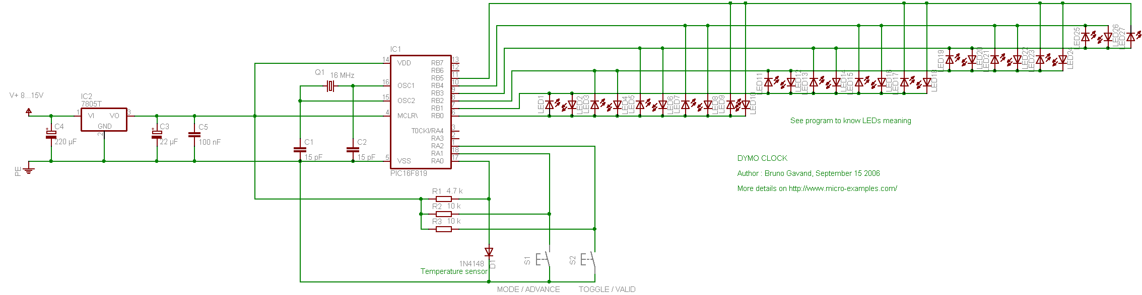
The PIC16F819 Dymoclock Sensor Circuit utilizes a PIC16F819 microcontroller, which is a versatile 8-bit device with built-in analog-to-digital conversion capabilities. This circuit is designed to monitor temperature variations and display the readings through LED indicators, making it a cost-effective solution for temperature sensing applications.
The circuit incorporates a low-cost temperature sensor, such as the LM35 or a similar device, which outputs a voltage proportional to the temperature. The microcontroller reads the analog voltage from the temperature sensor using its integrated ADC (Analog-to-Digital Converter). The ADC converts the analog signal into a digital value that can be processed by the microcontroller.
The LED indicators are used to visually represent the temperature readings. Each LED may correspond to a specific temperature range, allowing for a quick visual reference of the current temperature status. The absence of a decoder simplifies the design, reducing component count and potential points of failure, while also minimizing the overall cost of the circuit.
The operation of the circuit can be programmed using the PIC16F819's built-in features, allowing for flexibility in adjusting the temperature thresholds and LED indications. This makes the Dymoclock Sensor Circuit an ideal choice for applications where simple temperature monitoring is required, such as in weather stations, HVAC systems, or educational projects.
Overall, the PIC16F819 Dymoclock Sensor Circuit is a practical and efficient design that leverages the capabilities of the PIC microcontroller to create an effective temperature sensing solution with minimal components.The following circuit shows about PIC16F819 Dymoclock Sensor Circuit Diagram. Features: a cheap temperature sensor, only LEDs, no decoder, built .. 🔗 External reference
Related Circuits
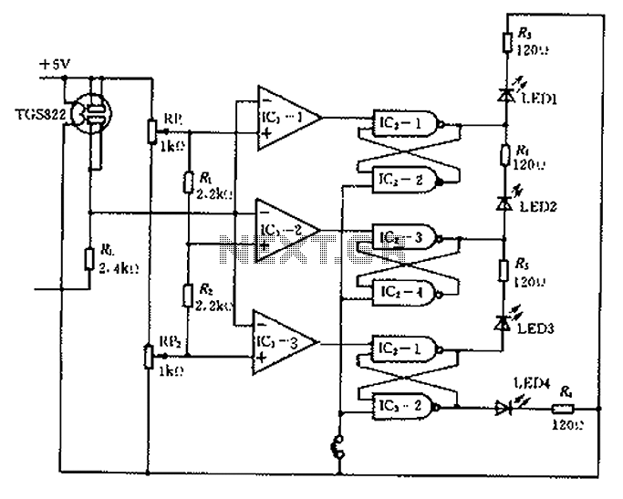
Ceramic gas sensors can be utilized to analyze the content of alcohol vapor. With the appropriate sensor circuit, it is possible to detect blood alcohol content. The operating principle is straightforward: if blood alcohol content is present in a...
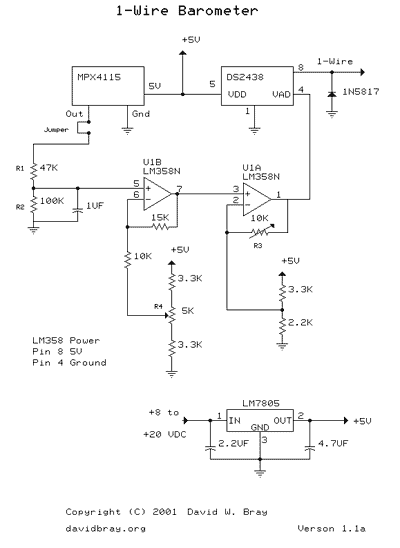
This design uses a Motorola MPX4115 Silicon Pressure Sensor, a Dallas Semiconductor DS2438 Smart Battery Monitor (to perform 1-Wire analog to digital conversion), an operational amplifier, a voltage regulator, a diode, and several resistors and capacitors. The circuit requires...
Several Hall Effect sensors are available for use with a BS2 microcontroller. One intended application is to count wheel rotations. A search for a schematic to connect these sensors to the BS2 has not yielded results. Assistance in providing...
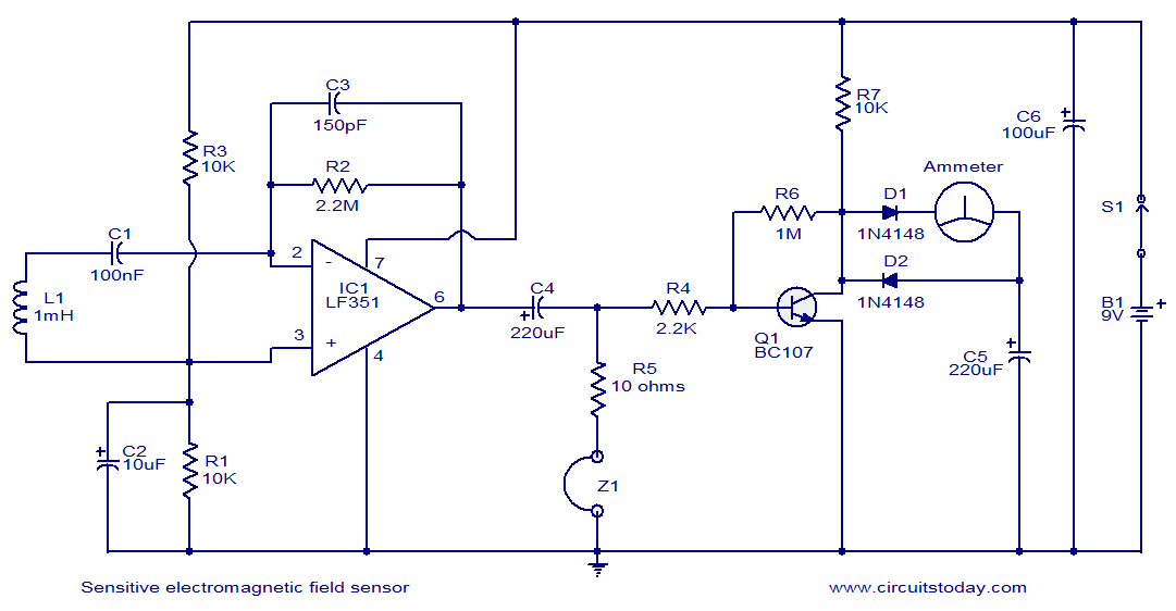
This circuit diagram represents a highly sensitive electromagnetic field sensor capable of detecting electromagnetic fields in the frequency range of 40Hz to 140Hz. The low-noise operational amplifier LF351, along with its associated components, comprises the pick-up section. A 1µH...
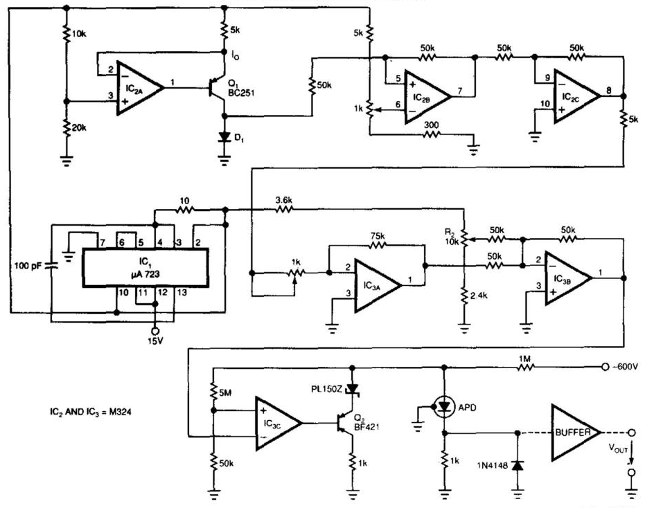
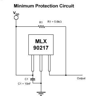
Laser-receiver circuits must bias their avalanche photodiodes (APD) to achieve optimal gain. Unfortunately, an APD's gain depends on the operating temperature. The circuit controls the operating voltage of an APD over a large temperature range to maintain the gain...

The circuit depicted in the schematic utilizes zero-drift operational amplifiers (LTC1250 and LTC1050) along with a precision instrumentation switched capacitor block (LTC1043). This design achieves exceptional DC accuracy down to microvolt levels. The choice of this method over a...
Warning: include(partials/cookie-banner.php): Failed to open stream: Permission denied in /var/www/html/nextgr/view-circuit.php on line 713
Warning: include(): Failed opening 'partials/cookie-banner.php' for inclusion (include_path='.:/usr/share/php') in /var/www/html/nextgr/view-circuit.php on line 713