
Simple Intercom circuit
The described circuit functions as a basic intercom system utilizing a 3-stage RC (resistor-capacitor) coupled amplifier configuration. The primary operation begins with the activation of switch S2, which initiates the amplifier circuit built around transistors T1 and T2. This arrangement is designed to operate as an asymmetrical astable multivibrator, a circuit configuration that generates a continuous square wave output. The frequency of this output can be adjusted by varying the values of the resistors and capacitors in the circuit, allowing for customization of the ring signal's characteristics.
Transistor T3 serves a crucial role in the circuit, as it amplifies the generated ring signals to a level sufficient to drive a speaker, typically an earpiece in this application. The low current consumption of 10 to 15 mA makes the system efficient, allowing the use of a 9-volt PP3 battery, which can provide extended operational life due to the minimal power requirements.
To create a two-way intercom system, two identical units are necessary. The design allows for the output from one amplifier unit to be routed to the speaker of the other unit, effectively enabling bidirectional communication. For a single-battery setup, the corresponding power and ground terminals of both units should be interconnected, simplifying the power supply arrangement.
The entire system, including components such as the microphone and earpiece, can be conveniently housed within the plastic casing of a cellphone toy. This design choice not only provides a compact and portable form factor but also utilizes readily available materials, making the project accessible for hobbyists and engineers alike. The suggested cellphone cabinet serves as an effective enclosure for the intercom circuitry, ensuring protection and ease of use.The circuit comprises a 3-stage resistor-capacitor coupled amplifier. When ring button S2 is pressed, the amplifier circuit formed around transistors T1 and T2 gets converted into an asymmetrical astable multivib-rator generating ring signals. These ring signals are amplified by transistor T3 to drive the speaker of earpiece. Current consumption of this intercom is 10 to 15 mA only. Thus a 9-volt PP3 battery would have a long life, when used in this circuit. For making a two-way intercom, two identical units, as shown in figure, are required to be used. Output of one amplifier unit goes to speaker of the other unit, and vice versa. For single-battery operation, join corresponding supply and ground terminals of both the units together. The complete circuit, along with microphone and earpiece etc, can be housed inside the plastic body of a cellphone toy, which is easily available in the market.
Suggested cellphone cabinet is shown. 🔗 External reference
Related Circuits
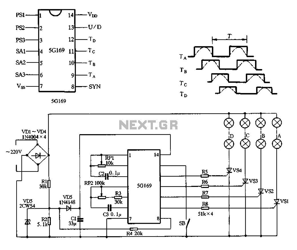
The circuit features an AC input from VDI, which is converted to pulsating DC power using a VD4 full-wave bridge rectifier to power four lights. Resistors R1 and R2, along with diode VD5, form a simple circuit, while VD6...
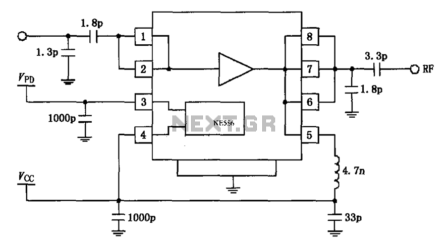
The circuit depicted in the figure is based on the RF2126, a 2450 MHz end-stage linear power amplifier. The radio frequency (RF) signal enters through input pin 1 and is subsequently amplified by the amplifier stages (pins 5, 6,...
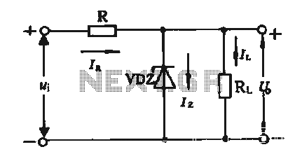
The simple voltage regulator circuit consists of a silicon regulator and a resistor. It is designed to rectify and filter DC voltage, as illustrated in the accompanying figure. The voltage regulator is connected in parallel with the load, and...
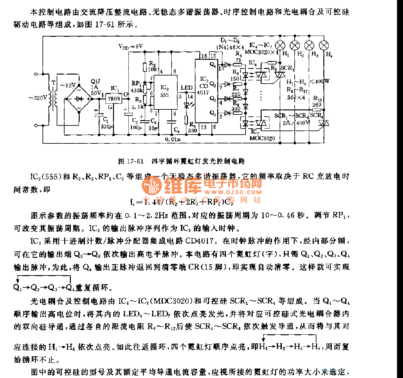
This control circuit consists of an AC step-down rectifier circuit, an astable multivibrator, a timing control circuit, an optocoupler circuit, and an SCR driving circuit, as illustrated in Figure 17-61. The astable multivibrator is formed using IC2 (555), resistors...
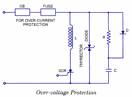
Silicon Controlled Rectifiers (SCRs) are sensitive to high voltage, over-current, and transients. To ensure satisfactory and reliable operation, they must be protected against such abnormal operating conditions. Due to the complexity and cost of protection mechanisms, devices with ratings...
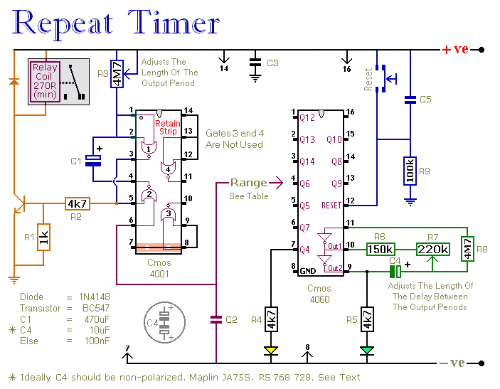
This circuit features an adjustable output timer capable of re-triggering at regular intervals. The output duration can range from a fraction of a second to over half an hour, and it can be configured to recur at regular intervals...
Warning: include(partials/cookie-banner.php): Failed to open stream: Permission denied in /var/www/html/nextgr/view-circuit.php on line 713
Warning: include(): Failed opening 'partials/cookie-banner.php' for inclusion (include_path='.:/usr/share/php') in /var/www/html/nextgr/view-circuit.php on line 713