
LM350 Regulator 3-Amp Adjustable
This circuit likely employs a variable voltage regulator or a similar topology that allows for a wide range of output voltages. The design may include adjustable resistors or potentiometers to fine-tune the output voltage within the specified range.
In a typical configuration, the input voltage should be higher than the maximum output voltage to ensure proper regulation. This could be achieved using a power supply with an output voltage of at least 15 volts to accommodate the dropout voltage of the regulator.
The circuit may also incorporate bypass capacitors at the input and output to stabilize voltage levels and filter out noise. These capacitors should be chosen based on the frequency response requirements of the application.
In addition, the use of heat sinks may be necessary if the circuit is expected to handle higher currents, as voltage regulators can dissipate significant power when stepping down voltage. The thermal performance of the device should be considered during design to prevent overheating.
The output voltage can be monitored using a multimeter or oscilloscope to ensure it operates within the desired range. Proper layout and grounding techniques should be employed to minimize electromagnetic interference and ensure stable operation.
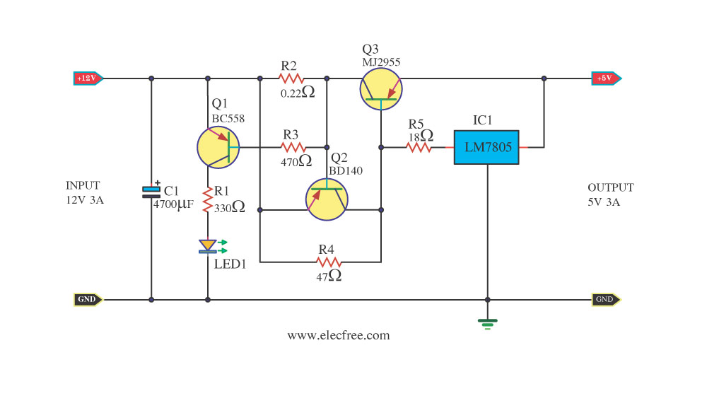
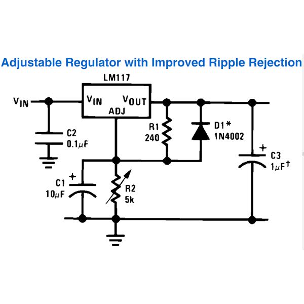
Overall, this circuit is versatile and can be utilized in various applications, including power supplies for sensors, microcontrollers, or other electronic devices requiring a stable voltage source.With the component values shown the circuit is designed to have and output voltage range of approximately 1.25 to 13.5 Volts when measured at the output of the.. 🔗 External reference
Related Circuits
A digital camera has been purchased that is capable of capturing both images and videos. However, it has been reported that the camera has limitations related to battery life, which affects its operational duration. The digital camera operates using a...
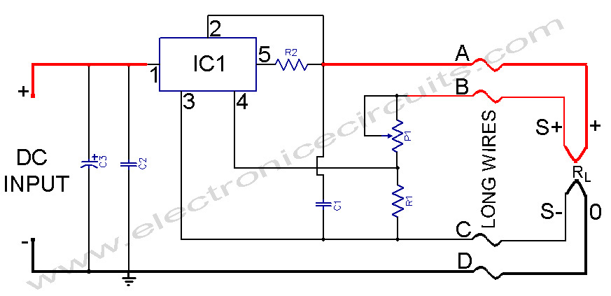
L200 Power Supply Regulator. There are applications in which it is important for the supply voltage to be largely independent of the load level. The L200 is a versatile voltage regulator designed to provide a stable output voltage while maintaining...
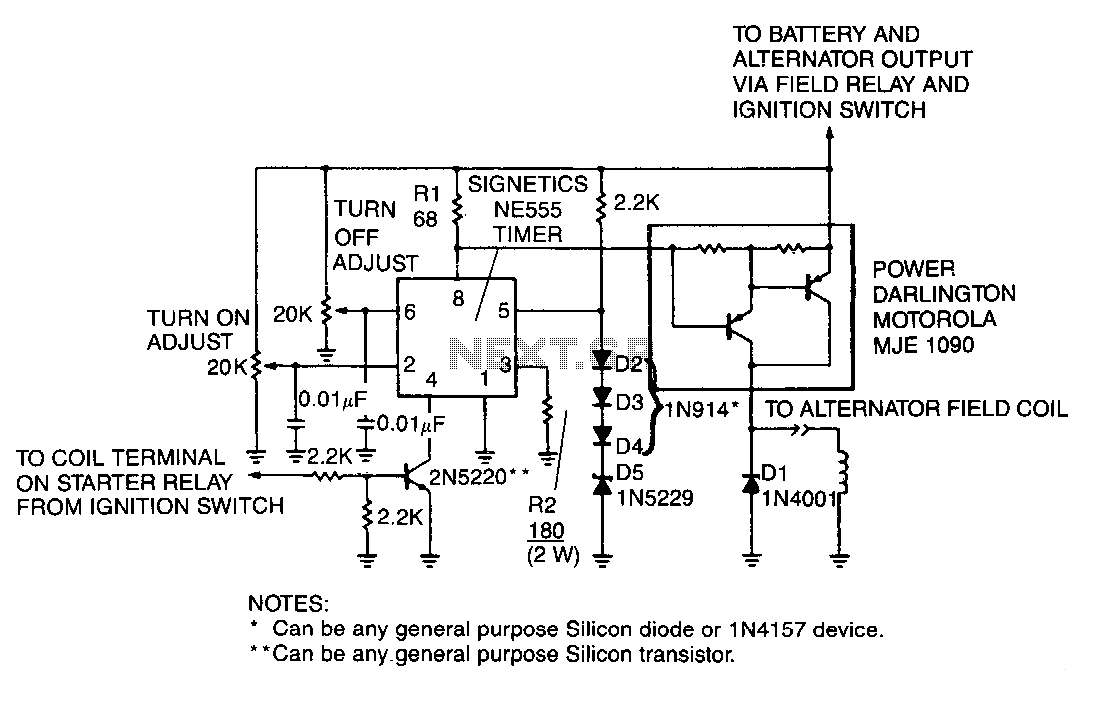
A monolithic 555-type timer serves as the core component of this straightforward automobile voltage regulator. When the timer is inactive, resulting in a low output at pin 3, the power Darlington transistor pair remains off. If the battery voltage...
This document outlines the process of constructing an adjustable power supply utilizing the LM317 integrated circuit (IC). The LM317 is highly versatile, allowing for the creation of a wide variety of compact, high-quality power supply circuits. Various configurations can...
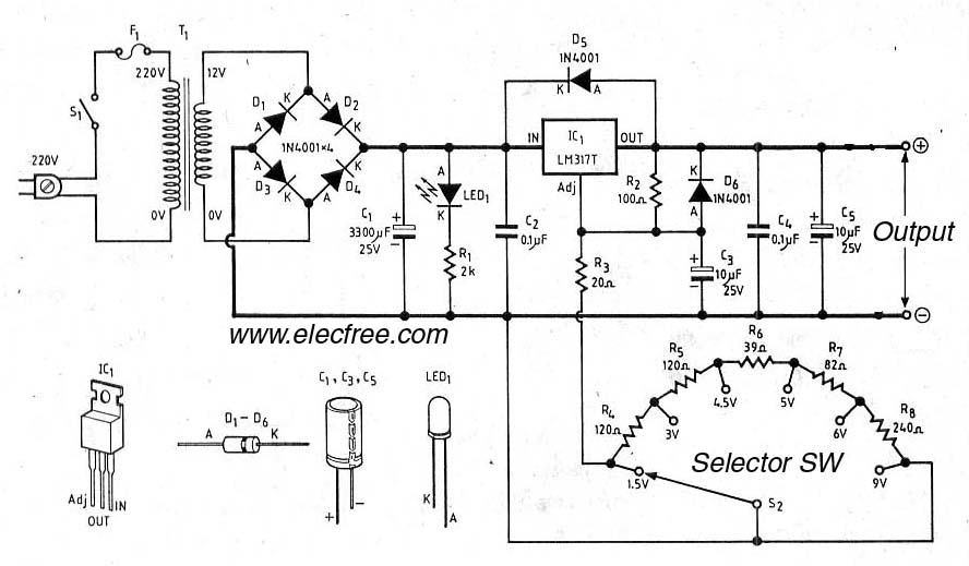
Typically, the study of electronic power supplies starts with batteries, such as 9 volts, 1.5 volts, and 6 volts. However, there are disadvantages associated with this approach. The exploration of electronic power supplies often begins with the use of batteries,...
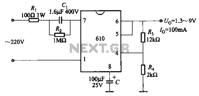
The output voltage can be calculated as follows: U = 1.3 (1 + R3 / R4) (V), where R3 and R4 are part of an adjustment potentiometer, allowing for a continuously adjustable output voltage. The described circuit involves a voltage...