
LM317 Adjustable Power Supply
The adjustable power supply circuit based on the LM317 IC is designed to provide a stable output voltage that can be varied according to the user's requirements. The LM317 operates as a linear voltage regulator, capable of delivering output currents up to 1.5 A with proper heat sinking. The output voltage can be adjusted between 1.25 V to 37 V, making it suitable for powering a wide range of electronic devices.
The essential components of the circuit include the LM317 IC itself, two resistors (R1 and R2), and capacitors for input and output stabilization. The resistor values are selected based on the desired output voltage, following the formula:
\[ V_{out} = V_{ref} \left(1 + \frac{R2}{R1}\right) + I_{adj} \cdot R2 \]
Where \( V_{ref} \) is typically 1.25 V, and \( I_{adj} \) is the adjustment pin current, which is usually negligible for practical purposes.
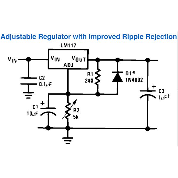
Input capacitors (typically 0.1 µF ceramic) are placed close to the input pin of the LM317 to filter out high-frequency noise, while an output capacitor (usually 10 µF electrolytic) is used to improve transient response and stability. A heat sink is necessary for the LM317 to dissipate heat generated during operation, especially when there is a significant voltage drop between the input and output.
The circuit can be powered by an unregulated DC voltage source, such as a transformer with a bridge rectifier. The maximum input voltage should not exceed 35 V to prevent damage to the LM317. The power supply's design allows for flexibility and adaptability, making it suitable for various applications, including powering microcontrollers, sensors, and other low to medium power electronic devices.
In summary, the LM317 adjustable power supply circuit is a robust solution for providing a regulated output voltage tailored to specific needs, combining simplicity in design with versatility in application.Here`s how to build your own adjustable power supply based on LM317. The IC LM317 is so versatile that an almost unlimited number of different, small, high grade power supply circuits can be built using it. The configurations can be introduced for different applications for upgrading an existing unit with features that would virtually make it indestructible.
A few useful application circuits using IC LM317, collected from National Semiconductor`s PDF datasheet are meticulously explained in this section with the help of the relevant circuit diagrams. All the circuits discussed below require an unregulated input voltage (max. 35 Volts) from any standard transformer/bridge/capacitor network 🔗 External reference
Related Circuits
Powered by a solar panel, the circuit provides a 5V pure regulated DC voltage. It consists of an oscillator transistor and a regulator transistor. The solar panel charges the battery when sunlight is sufficient to generate a voltage above...
A simple 9 Volt, 2 amp power supply utilizing a single integrated circuit (IC) regulator. This circuit is straightforward, as the regulator handles the majority of the work. The component used is the 7809 voltage regulator. The circuit consists primarily...

The following circuit is a power amplifier circuit for an FM transmitter with an output power of 30 watts. The power amplifier circuit utilizes a power transistor of type 2SC1946A. The FM transmitter operates with a 13.8-volt DC power...
The main feature of this power supply is its selection of outputs at standard fixed voltages commonly used in electronics. Since the outputs are fixed, there is no need to worry about voltage correctness; simply plug in the wire...
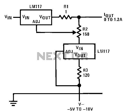
This circuit illustrates an adjustable regulator configuration that incorporates a voltage regulator. In this design, the LM117 regulator is utilized instead of the LM113 diode for reference. Both regulators necessitate a negative supply to function correctly with respect to...
If the sensor system requires an active supply, a single pair of cables can be utilized to transmit both the power supply and the output signal. This approach simplifies the overall system. In sensor systems that necessitate an active power...