
LM3914 LM3915 20 Led Stereo Vu Meter
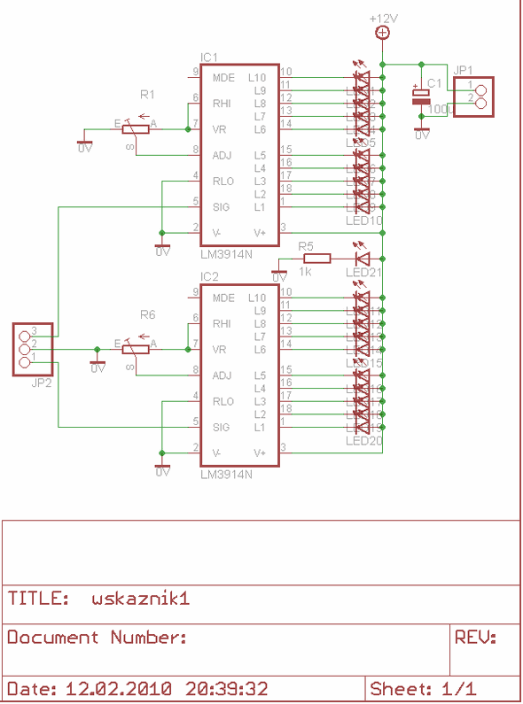
The LM3914 is widely utilized in audio applications to visually represent audio signal levels through LED indicators. This integrated circuit can operate in either bar graph or dot display modes, allowing for flexibility in design based on user requirements. It is capable of driving up to 10 LEDs in a single string, making it suitable for stereo applications where two sets of 10 LEDs can be used to indicate left and right channel levels.
The typical application of the LM3914 involves connecting the analog voltage input to the reference pin, which sets the scale for the LED display. The IC can be powered using a standard voltage supply, typically ranging from 3V to 30V, which facilitates its use in various electronic projects. The output pins are designed to drive standard 5mm or 10mm LEDs, which can be configured to display the audio levels in a visually appealing manner.
For PCB design, the use of Eagle software allows for precise layout and routing of the circuit. The schematic for the 10 LED stereo VU meter includes connections for the power supply, input signal, and LED outputs. Proper attention must be paid to the grounding and power distribution to ensure accurate readings and reliable operation. The design can also incorporate additional components, such as resistors and capacitors, to filter the input signal and stabilize the LED display.
In summary, the LM3914 integrated circuit provides an effective solution for creating a stereo VU meter, with its ability to drive multiple LEDs and adapt to various voltage levels, making it a valuable component in audio signal visualization. The Eagle PCB layout facilitates the creation of a compact and efficient circuit, suitable for both hobbyist and professional applications.LM3914 Dot Bar Display Driver LM3914 is a monolithic integrated circuit that senses analog voltage levels and drives 20 Led stereo Vu Metre Devresi PCB Circuit LM3914 10 leds stereo vumeter circuit diagram of Eagle PCB drawing of eagle 🔗 External reference
Related Circuits
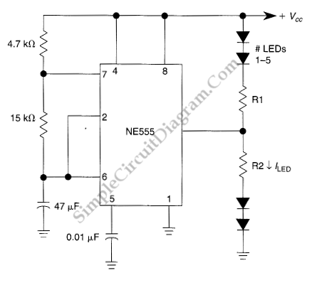
This LED flasher circuit utilizes a 555 integrated circuit (IC) and is designed to drive multiple LEDs. Notably, connecting several LEDs in series does not increase the power consumption. The LED flasher circuit based on the 555 timer IC is...
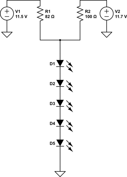
A series of LEDs is intended to display at two brightness levels, and there is uncertainty regarding the proper wiring. This setup is for additional running lights and brake lights on a bicycle. When using the series LED calculator,...
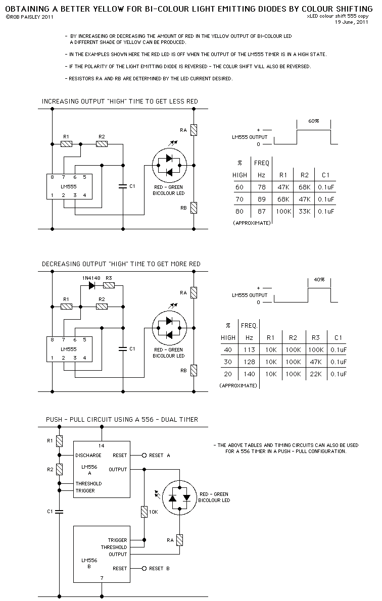
These circuits provide a means of altering the YELLOW output of RED / GREEN type two colour light emitting diodes. These circuits use the LM555 timer chip. The circuit described utilizes the LM555 timer integrated circuit (IC) to modulate the...

This simple mock flasher LED simulates the indicator of a sophisticated alarm system. It can be placed in doors, gates, and vehicles to confuse intruders. The mock flasher LED circuit is designed to mimic the flashing behavior of a typical...
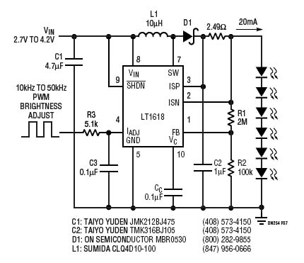
The LT1618 not only provides an accurate input current limit but also functions as a regulated output current source suitable for current-source applications. One such application is driving white LEDs, for which the LT1618 is particularly well-suited. It operates...
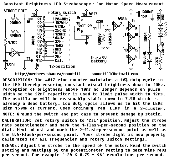
The rotary switch is available for $5.00USD as of 2003 from DigiKey under part number EG1951-ND or EG1952-ND. It is a real pain to operate this circuit without a proper switch. You can put multiple 4017 ring counters in...
Warning: include(partials/cookie-banner.php): Failed to open stream: Permission denied in /var/www/html/nextgr/view-circuit.php on line 713
Warning: include(): Failed opening 'partials/cookie-banner.php' for inclusion (include_path='.:/usr/share/php') in /var/www/html/nextgr/view-circuit.php on line 713