
LM555 Timer Delay Signal Clock Circuit
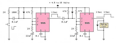
The LM555 timer is a versatile integrated circuit widely used in various timer, delay, pulse generation, and oscillator applications. In this specific configuration, the circuit utilizes two stages to enhance its functionality. The first stage is responsible for generating a precise pulse width, while the second stage manages the delay period between pulses.
The circuit is typically configured in astable or monostable mode, depending on the desired output behavior. In astable mode, the LM555 continuously oscillates between high and low states, generating a square wave output. This configuration is ideal for applications such as clock pulses, LED flashers, or tone generation.
In monostable mode, the LM555 produces a single pulse of a specified duration in response to a trigger input. This mode is useful for applications requiring a timed response, such as timer circuits or event counters.
Key components in the circuit include resistors and capacitors that determine the timing characteristics. The pulse width is primarily influenced by the values of the resistors and the capacitor connected to the discharge and threshold pins of the LM555. Similarly, the delay period can be adjusted by modifying the component values in the feedback loop.
Overall, the dual-stage design of this LM555 timer circuit enhances its versatility, allowing for precise control over both pulse width and delay, making it suitable for a wide range of electronic applications.LM555 timer circuit is similar to the one above but employs two stages so that both the pulse width and delay can be controlled 🔗 External reference
Related Circuits
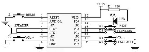
This tutorial focuses on the MP3 mode of the WTV020SD-16P module. With this straightforward circuit, AD4 format music files can be played. A video demonstration of this simple project is available at the end of the article. The project...
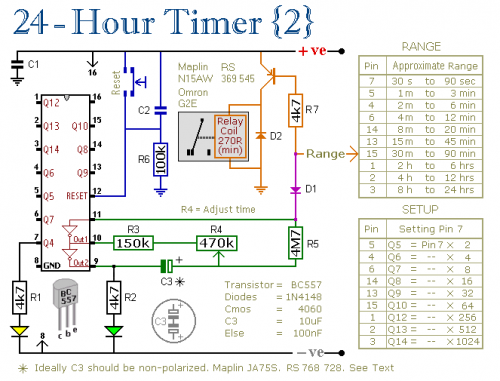
A pair of multi-range timers that provide timing periods of up to 24 hours and beyond. Both timers are fundamentally similar, with the primary distinction being that Version 1 energizes the relay when the time expires, while Version 2...
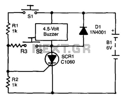
A self-interrupting device connected to a voltage source operates as a switch that continuously opens and closes; thus, the circuit does not latch in the conventional manner, allowing the alarm to function only while switch SI is closed. Due...
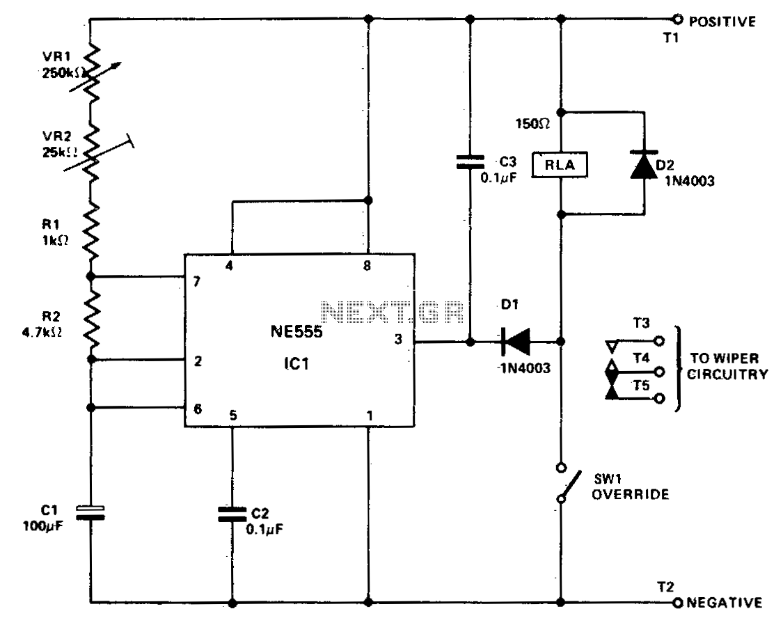
IC1 is configured in astable mode, controlling relay RLA. Capacitors C3, diodes D1 and D2 are utilized to prevent voltage spikes from the relay coil and the wiper motor from activating IC1. Variable resistor VR2 is set to provide...
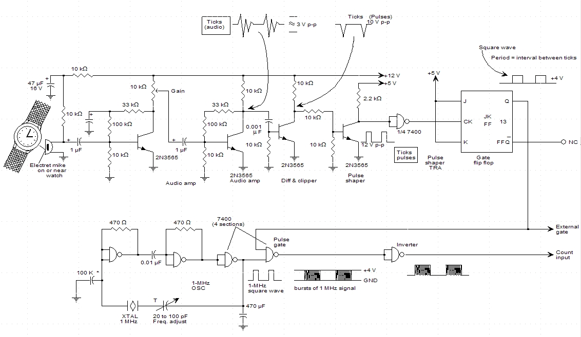
A schematic for a watch timer was found in a hobby electronics book. The circuit adapts a frequency counter to measure intervals. Watch ticks are clipped, shaped, and formed into a square wave. This square wave is utilized to...
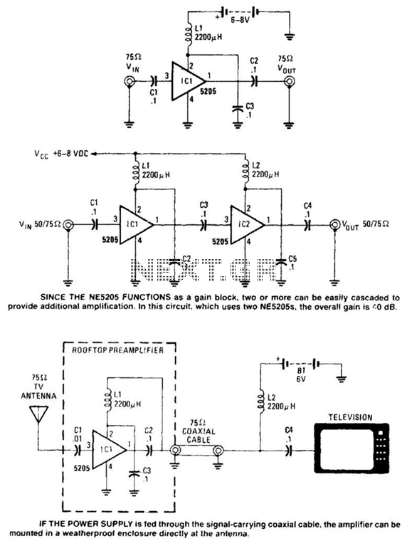
Except for the coupling and decoupling capacitors, IC1 is a complete wideband amplifier that has a fixed gain of 20 dB up to 450 MHz. No external compensation is required. Since the NE5205 functions as a gain block, two...
Warning: include(partials/cookie-banner.php): Failed to open stream: Permission denied in /var/www/html/nextgr/view-circuit.php on line 713
Warning: include(): Failed opening 'partials/cookie-banner.php' for inclusion (include_path='.:/usr/share/php') in /var/www/html/nextgr/view-circuit.php on line 713