
Watch Timer circuit
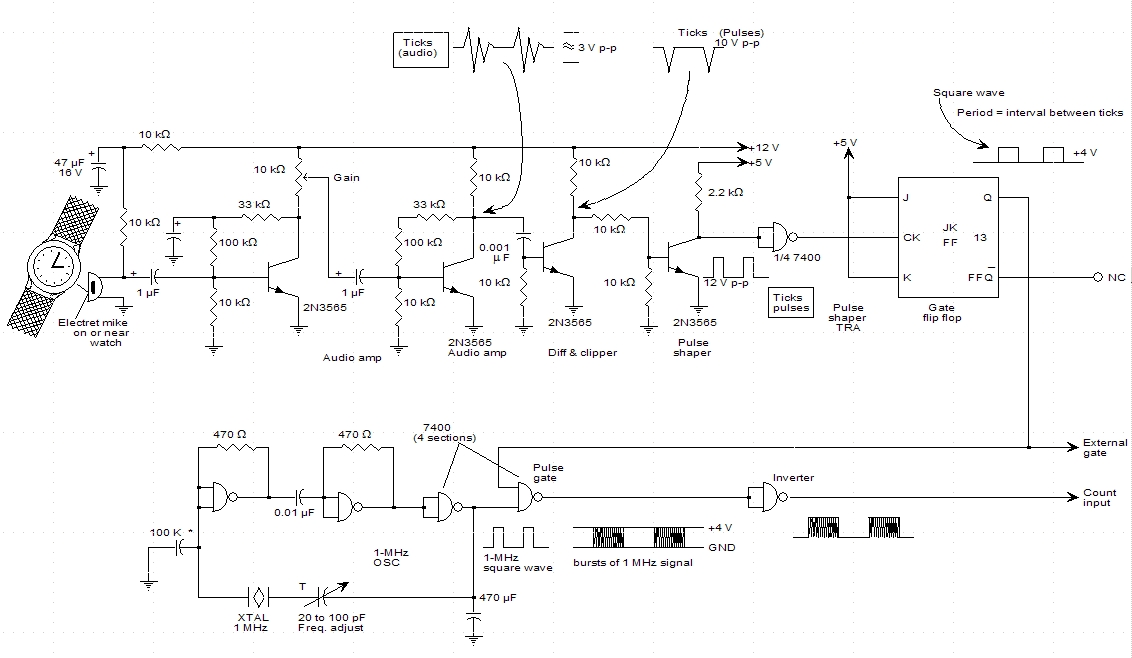
The described circuit serves as a timer that leverages the precision of a frequency counter to measure time intervals based on the ticks of a watch. The process begins with the detection of the watch ticks, which are typically analog signals. These signals are then processed through a clipping and shaping stage to convert them into a clean square wave. This transformation is critical as it ensures that the frequency counter receives a signal that is suitable for accurate measurement.
The square wave generated from the watch ticks is used to control the gating of a 1 MHz TTL (Transistor-Transistor Logic) crystal oscillator. The oscillator serves as a stable and accurate time reference. By using a TTL crystal oscillator, the circuit benefits from low power consumption and high reliability, which are essential characteristics for hobby electronics projects.
An external counter is integrated into the system to tally the number of clock pulses produced by the oscillator during the time intervals defined by the watch ticks. This external counter can be any digital counter capable of handling the frequency output from the oscillator. The output from the counter can then be displayed on a digital readout or used for further processing, depending on the design requirements.
In summary, this circuit design effectively combines the principles of frequency counting and signal processing to create a functional watch timer. Its simplicity and reliance on widely available components make it an attractive project for hobbyists looking to deepen their understanding of electronics and timing circuits.Hello all, I ran across this schematic for a watch timer in a hobby electronics book. Anyone built something like this before? My knowledge of electronics is somewhat limited. Here is the description: ""This circuit adapts a frequency counter to measure intervals, watch ticks are clipped and shaped and formed into a square wave. This square wave is used to gate an accurately known clock (1 Mhz TTL XTAL OSC) and an external counter is used to directly count the clock pulses during the..
🔗 External reference
Related Circuits
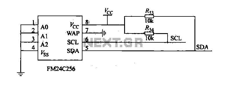
The FM24C256 is utilized as a slave interface circuit in an I2C bus configuration, with the address format specified in Table 27-3. The address pins A2, A1, and A0 are set to low; however, for extended storage capacity, adjustments...
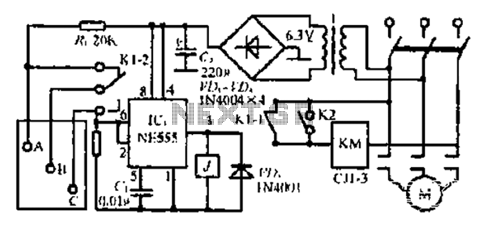
After the 3.40V power supply, the voltage is reduced to 6.3V through a full transition rectification using VDi and V sulfone. The C1 filter provides voltage stabilization after the caution circuit operates at the NE555 voltage level. When the...
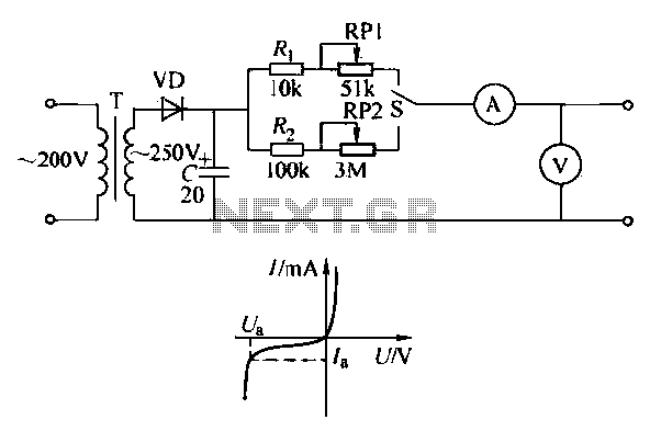
To ensure proper operation of the transistor in a circuit, it is essential to measure the reverse breakdown voltage of the transistor. This is particularly important for tubes with high reverse breakdown voltage requirements, such as those used in...
The circuit diagram of this programmable sequencer can be utilized for various timing applications. An audible tone is generated before the start of each interval, while a seven-segment LED display indicates the current interval number. A buzzer sounds again...
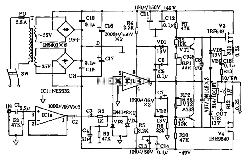
The amplifier circuit presented in this paper introduces a floating power supply aimed at increasing output power. The output power of the amplifier is influenced primarily by the final stage amplifier supply voltage. The circuit's principle is illustrated in...
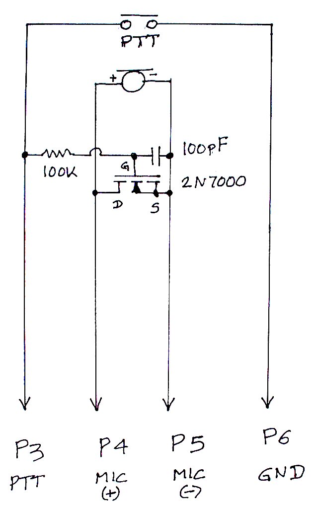
The TS-440S, similar to several other radios, does not mute the microphone when utilizing the rear audio connector for digital modes. Consequently, unless the microphone is unplugged each time digital modes are used, background noise from the shack can...