
Scr Circuit With Self-Interrupting Load
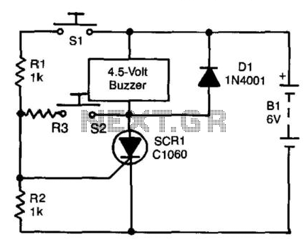
The described self-interrupting device circuit primarily consists of a switch (SI), an alarm, a silicon-controlled rectifier (SCR), a damping diode (D1), and a resistor (R3) along with the additional 470-ohm resistor for latching functionality. The device operates by maintaining a continuous cycle of opening and closing, which prevents the alarm from latching in a traditional sense. This behavior is crucial for applications requiring temporary alerts or notifications.
The damping diode (D1) serves a critical role in protecting the circuit from voltage spikes generated by the inductive load. When the alarm is triggered, the inductor's collapsing magnetic field can induce a high-voltage spike, which could potentially damage other components within the circuit. The diode provides a path for this induced current, effectively clamping the voltage and safeguarding the SCR and other sensitive elements.
For self-latching operation, the addition of a 470-ohm resistor in parallel with the alarm modifies the circuit's response. When the alarm is activated, the SCR is turned on, allowing current to flow through the alarm and the added resistor. The current through the resistor keeps the SCR in a conductive state even after the initial trigger from switch SI is removed. The value of R3 plays a significant role in determining the minimum current required to keep the SCR latched. If the current falls below this threshold, the SCR will turn off, and the alarm will cease to sound.
To reset the circuit and deactivate the alarm, switch S2 is employed. Pressing S2 allows the anode current to drop to zero, effectively un-latching the SCR. This mechanism is essential for reactivating the alarm system when needed and ensures that the device can be used repeatedly without manual intervention.
Overall, this circuit design offers flexibility in alarm functionality, allowing it to operate in both momentary and latching modes, making it suitable for various applications in alarm systems and safety devices. A self-interrupting device connected to a voltage source functions as a switch that repeatedly open s and closes; therefore, the circuit does not latch in the normal way, so the alarm operates only as long as SI is closed. Because of the inductive nature of that type of load, a damping diode (Dl) must be wired across it. The circuit can be modified to provide a self-latching action simply by wiring a 470- resistor in parallel with the alarm.
The circuit latches because the anode current of the SCR does not fall to zero when the alarm self-interrupts, but to a value that is determined by the value of the R3. The circuit can be unlatched by pressing S2, thereby enabling the anode current to fall to zero when the alarm self-interrupts.
🔗 External reference
Related Circuits

The sensor must be positioned at an angle of approximately 30 to 45 degrees relative to the ground. This orientation facilitates the drainage of rainwater, preventing accumulation that could trigger the alarm due to water retention on the sensor....

Digital Command Control (DCC) provides significant advantages over traditional DC analog control systems, primarily due to its simplified wiring. DCC enables the individual control of multiple locomotives on the layout without requiring electrical isolation of track sections. The main...
Most of the power supply failure indicator circuits need a separate power supply for themselves. But the alarm circuit presented here needs no additional supply source. It employs an electrolytic capacitor to store adequate charge, to feed power to...
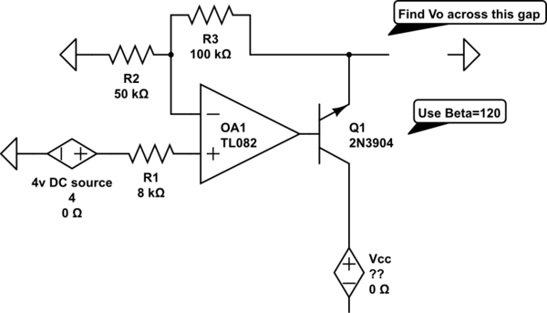
The voltage measured at 12V after the emitter is perplexing, especially when the output from the op-amp is +15V, suggesting a 3V drop across the transistor. This raises questions about the expected gain of 2, which would imply an...
The circuit features a serial coded modulated control signal that amplifies and transmits high-voltage isolation. It utilizes a 556 timer-based circuit along with resistors R1, R2, capacitors C1, and R3, R4, C2 to form two astable multivibrators. The circuit...
This project involves outdoor LED solar garden lights, which function as an automatic garden lighting system utilizing a light-dependent resistor (LDR) and a 6V/5W solar panel. During daylight hours, the internal rechargeable 6 Volt sealed lead-acid (SLA) battery is...