
lm7805 5v regulator for usb phone charging
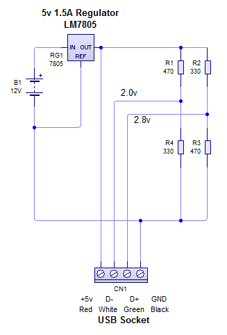
The circuit design features two voltage dividers, which are essential for providing specific voltage levels to different parts of the system. A voltage divider consists of two resistors connected in series, where the output voltage is taken from the junction between the two resistors. This configuration allows for precise control over the voltage levels delivered to the designated nodes in the circuit.
In this prototype, the first voltage divider is configured to output 2.0V, which is connected to the D- terminal. The choice of resistor values for this divider must be calculated to ensure that the output voltage remains stable under varying load conditions. The second voltage divider outputs 2.8V, which is likely intended for a different component that requires a higher voltage level for optimal operation.
The overall circuit layout should be carefully designed to minimize noise and ensure reliable performance. Proper bypass capacitors may be included near the voltage divider outputs to filter out any high-frequency noise that could affect the voltage levels. Additionally, the circuit should be tested under various conditions to verify that the voltage levels remain within the required specifications, ensuring the functionality and reliability of the prototype.
Furthermore, it is important to consider the power ratings of the resistors used in the voltage dividers. They must be rated appropriately to handle the power dissipation without overheating. The prototype should also be evaluated for thermal performance to ensure that all components operate within safe temperature limits during extended use.
In summary, this prototype circuit represents a fundamental approach to voltage regulation using simple voltage dividers. Future iterations may include more advanced techniques such as operational amplifiers for improved voltage stability or the integration of feedback mechanisms to dynamically adjust the output voltages based on load conditions.Right! Now that I have finally solved the issue on the charging here is prototype 1 of the circuit. It uses 2 voltage dividers to give 2.0v to D- and 2.8v to.. 🔗 External reference
Related Circuits
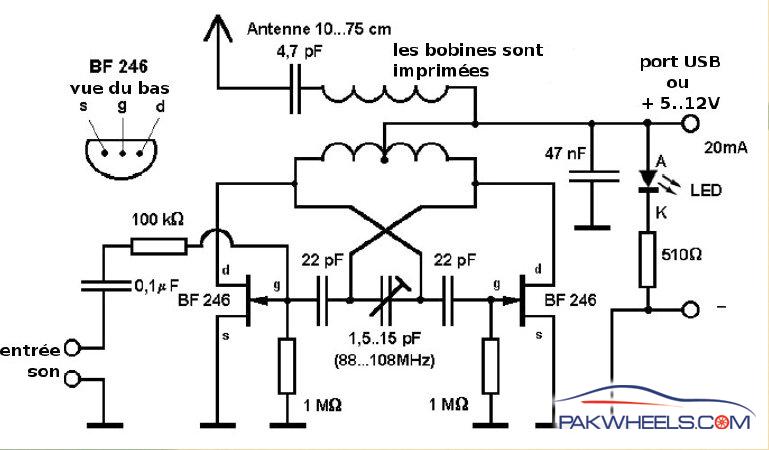
A USB-powered laptop FM transmitter designed for home theater systems and other woofers equipped with FM receivers. It transmits music from a laptop to the sound system in a room. The USB-powered laptop FM transmitter operates by converting audio signals...
Building a headphone amplifier is like building a power amp - only the current demand is just a little bit lower (about a factor 100). Various designs can be found in the internet, and it is relatively easy to...
This preamplifier amplifies the signal from a microphone, an amplifier so that it can be further strengthened. The circuit supplies an output signal line. With two transistors, it is not difficult to build such a circuit. The amplifier produces...
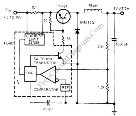
Switching voltage regulator utilizing the TL497 integrated circuit, achieving up to 75% efficiency. The output voltage is 5V, while the input voltage ranges from 7.5V to 15V. The TL497 is a versatile integrated circuit designed for use in switching voltage...
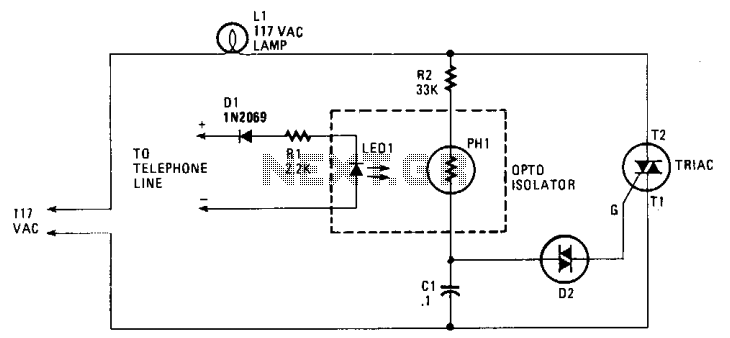
When the phone rings, the triac is activated into conduction by a signal applied to its gate (G) through a bilateral switch (diac), D2. The triac functions as a switch, conducting only when a signal is present at the...
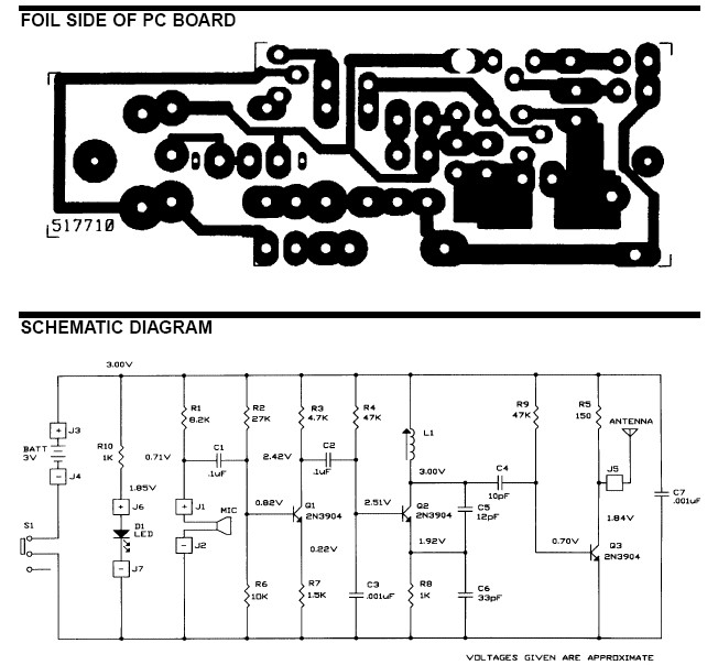
The frequency range for the FM transmission band is 90 MHz (megahertz, or 90 million cycles per second). Due to the variable tuned circuit in the FM transmitter, it can be tuned to a specific frequency within the local...