
Basic Microphone preamplifier
This preamplifier circuit is designed to amplify low-level audio signals from microphones, enabling further processing or amplification stages. The circuit utilizes two transistors, specifically the BC549C and BC547B, which are common choices for audio applications due to their low noise characteristics and high gain.
The circuit configuration typically consists of a differential amplifier stage formed by the two transistors, which helps to minimize noise and enhance the signal-to-noise ratio. The input impedance is critical for microphone compatibility, and in this design, it is suitable for microphones with an impedance ranging from 500 to 600 ohms. Resistor R1, typically set at 470 ohms, may be adjusted to 220 ohms for specific microphone types to optimize performance.
Capacitor C1, initially suggested as 2.2 µF, can be increased to 4.7 µF to improve low-frequency response and coupling, ensuring that the audio signal passes through without significant attenuation. The gain of the amplifier is primarily determined by resistor R2, which is set to 22 kOhms for a maximum gain of approximately 200 times. This high gain is essential for amplifying weak signals from microphones to a level suitable for further processing.
Additional resistors (R3 to R8) are included to stabilize the circuit, set biasing conditions, and control the gain across different operating conditions. Capacitors C2 and C3 serve to filter out unwanted noise and stabilize the power supply, while C4 provides additional coupling and decoupling capabilities.
This preamplifier circuit is an effective solution for audio applications, ensuring that microphone signals are amplified with minimal noise and distortion, making it suitable for various audio processing tasks.This preamplifier amplifies the signal from a microphone, an amplifier so that it can be further strengthened. The circuit supplies an output signal line. With two transistors, it is not difficult to build such a circuit. The amplifier produces noise Weining. In the drawn embodiment the circuit suitable for microphones from 500 to 600 ?. R1 200 ? for microphones should be reduces to 220 ? and C1 should be increased to 4.7 uF. The gain is set by R2. If the average declared value of 22 kOhm used. The maximum gain is about 200 times. Parts List R1 = 470 ? R2 = 22 kOhm R3 = 12 kOhm R4 = 47 kOhm R5 = 820 ? R6 = 100 ? R7 = 1 kOhm R8 = 100 kOhm C1, C4 = 2.2 V ?F/16 C2 = 47 V ?F/16 C3 = 470 nF T1 = BC 549C T2 = BC 547B 🔗 External reference
Related Circuits
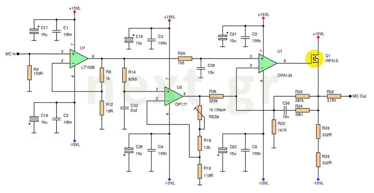
This microphone preamplifier circuit enhances the acoustic signal of a moving coil microphone (MC) with a sensitivity of 150μV at line level. In this design, a specific technique is not employed because the noise produced does not significantly impact...
AM radio receivers demodulate amplitude-modulated (AM) signals. The primary source of these signals is the Standard AM Radio Broadcast Band, although shortwave stations also utilize AM modulation. Amplitude modulation was developed between 1900 and 1917 by amateur radio enthusiasts....
A lot of friends asked me to draw a more shrunk circuit 2-ch mixer, which will contain also, operation CROSSFADER. The circuits can be modified and added also other channels, repeating basic that I give. It can be added...
The circuit utilizes two 2N3819 FETs configured in a cascode arrangement. The lower FET functions in common source mode, while the upper FET operates in common gate mode, achieving full high-frequency gain. The lower FET is tunable, enabling peak...
The purpose of this circuit is for research and education. Assistance is sought in acquiring components for simple RF circuits, as well as tutorials or schematics. The requester is facing challenges in locating quality resources for beginner-level RF circuit...
The concept of a color organ involves the transformation of sound, including musical tones, into light. According to wave theory, both music and light possess similar wave characteristics. A color organ is an electronic device that visually represents sound through...
Warning: include(partials/cookie-banner.php): Failed to open stream: Permission denied in /var/www/html/nextgr/view-circuit.php on line 713
Warning: include(): Failed opening 'partials/cookie-banner.php' for inclusion (include_path='.:/usr/share/php') in /var/www/html/nextgr/view-circuit.php on line 713