
Locked Loop Synchronous Demodulator
The described circuit implements a synchronous demodulator utilizing a phase-locked loop (PLL) architecture to effectively lock onto and demodulate a 7-bit Barker code signal. The microcontroller, specifically the ATtiny2313, serves dual roles as both a voltage-controlled oscillator (VCO) and a Barker code generator. The PLL configuration allows for precise frequency locking to the incoming signal, enhancing the circuit's ability to reject noise while maintaining the integrity of the demodulated output.
The circuit operates from a single positive power supply, simplifying the design and reducing component count. The ATtiny2313 microcontroller generates three time-shifted Barker code outputs, which appear as open-drain outputs to external circuitry. This timing arrangement is crucial for synchronizing the demodulation process with the incoming signal. The microcontroller's internal 8-bit timer triggers interrupts to initiate code generation, providing ample time for additional control and computational tasks, such as modulating the Barker code with data or decoding incoming streams.
A quad op-amp, such as the LM324, is employed in the circuit to amplify the demodulated signal, extending the output range to operate near ground level. This is particularly beneficial for applications requiring low-voltage operation. The circuit's design includes a switched resistor demodulator, which minimizes the number of required components while still achieving effective signal demodulation.
The implementation of the circuit was validated through experimental setups, which included the use of an infrared LED driven by a second microcontroller (ATtiny12) to emit the Barker code sequence. A photodiode was used to capture the emitted light, allowing for the demodulation of the signal without direct electrical connections between the beacon and the demodulator. This method demonstrates the circuit's ability to operate effectively in real-world scenarios, including those where the signal source is battery-operated.
The testing procedure involved adjusting the free-run frequency of the demodulator to closely match the frequency of the incoming Barker code signal. Oscilloscope measurements were taken to ensure proper synchronization and to visualize the performance of the demodulator. The results indicated successful locking onto the incoming signal, thereby confirming the efficacy of the circuit design in achieving robust modulation and demodulation for RF communications.
This circuit represents a significant advancement in synchronous demodulation technology, reducing component complexity while enhancing performance characteristics such as noise rejection and processing gain. Future iterations could explore the use of longer Barker codes and faster chip rates to further improve performance, demonstrating the circuit's scalability and adaptability for various applications in communication systems.A simple, low component count phase locked loop that locks onto and detects the amplitude of an incoming baseband 7 bit Barker code using a switched resistor demodulator that is driven directly by a microcontroller's output pins. Balanced modulators using resistors and a microcontroller's output pins. Locking into oncoming Pseudo-noise (PN) stream. Microcontroller modulates its own crystal oscillator frequenc inside a Phase-Locked Loop (PLL). Extending the output range of a bipolar op-amp to opearte near ground. The only semiconductors in the circuit are the microcontroller and a quad opamp. This picture was taken before the offset adjustment for the signal level measurement circuit was installed. Some surface mount components are on the other side of the board. After a successful synchronous demodulator project, as described in Digital Lock-in Milliohmmeter and Experimental 1 kHz Synchronous Demodulator, I looked for a way to improve upon on the basic synchronous demodulator that I used in those projects.
I was looking for a way to reduce the component count, eliminating the transmission gates if possible. I also wanted the demodulator to be able to lock to signal from a remote source, all the while maintaining the benefits of noise rejection and processing gain that one would expect from a synchronous demodulator, because such a circuit might lead to a simple but robust modulation and demodulation scheme for RF communications.
The circuit in figure 1 is that of a synchronous demodulator that meets these requirements, and additionally, it operates from a single positive power supply. The circuit will be described in detail later in this page. The ATtiny2313 microcontroller is used as a voltage controlled crystal oscillator and Barker code generator, and could be replaced with small scale logic devices.
The code generation is initiated by interrupts from the microcontroller's internal 8 bit timer, and there is plenty of time available for control and computational tasks that could used to modulate the Barker code stream with data or to decode an incoming stream. The ATtiny2313 has three Barker code outputs, shifted one half of a chip in period (the time period allotted to one bit in the Barker code) from one-aonther, that appear to the external circuitry as though they are open drain outputs, it has three regular CMOS outputs that are similarly time shifted with respect to one another, and it has a sync output that occurs one time with each repetition of the Barker code.
The sync signal is to facilitate testing of the circuit. This implementation, using a 7 bit Barker code with a 148 microsecond chip rate, was intended as a means of proving a concept. The low chip rate was selected because it is easy to deal with using the inexpensive equipment available to me.
A longer Barker code and a faster chip rate would increase performance, and merely scaling the design will provide those improvements.As a test signal source, I programmed an ATtiny12 microcontroller with code similar to the ATtiny2313 and uses its code output pin to drive a gated constant current source, which in turn drives an infrared LED with 50 milliamps. The LED emitted light in accordance with the Barker code sequence sent from the chip. As with the ATtiny2313, this function could be easily replaced with discrete logic. In addition to the code output, the ATtiny12 also has a sync output that occurs one time with each repetition of the Barker code.
In an experiment to visually illustrate operation of the demodulator, I connected a photo diode between the signal input and "ground" on the demodulator circuit in Figure 1 and used the 7 bit Barker code beacon shown in Figure 2. There was no electrical connection between the beacon and the demodulator, except that their power supplies were plugged into the same electrical outlet.
During some experiments, the beacon was battery operated, and I did not notice any difference in performance between those experiments in which the beacon was battery operated and those experiments in which the beacon was powered from a power supply. Before testing, the free run frequency of the demodulator had to be set. Channel one of a Tektronix TDS-2002 oscilloscope was connected to the punctual Barker code output pin on the ATtiny2313 (ATtiny2313 pin 18), and scoope was sync'd to the sync output of the ATtiny2313 (ATtiny2313 pin 16).
Channel two of the scope was connected to the Barker output of the ATtiny12 on the beacon assembly (ATtiny12 pin 7) and the infrared LED on the beacon was covered so demodulator would not detect the beacon's signal. While simultaneously viewing the prompt Barker code generated on the demodulator and the Barker code generated by the beacon, the free run frequency of the demodulator was adjusted so that rate of local prompt Barker code generation was fraction of a word per second slower than that of the beacon.
Channel two of a Tektronix TDS-2002 oscilloscope was then moved to the output of the voltage follower stage in the demodulator (LM324 pin 8) and the IR LED on the beacon was uncovered. letting some of the light from the LED fall on the photo diode connected to the demodulator. 🔗 External reference
Related Circuits
All ATL-3 loop windings are center-tapped and balanced with respect to their amplifier/receiver chassis ground, which leads to self-cancellation of electric field interference. Magnetic noise fields, such as those from televisions and electric meter boxes, or electromagnetically radiated interferences,...
An AM loop antenna is one of the true marvels of electronics. Requiring no power, it takes advantage of the resonant properties of an inductor and a capacitor connected in parallel to receive weak AM stations. The "loop" part...
The material is presented as a teaching tool aimed at enhancing understanding and interest in the design of counters. According to R. S. S. Obermann, the design of counters serves as an excellent proving ground for individuals who have...
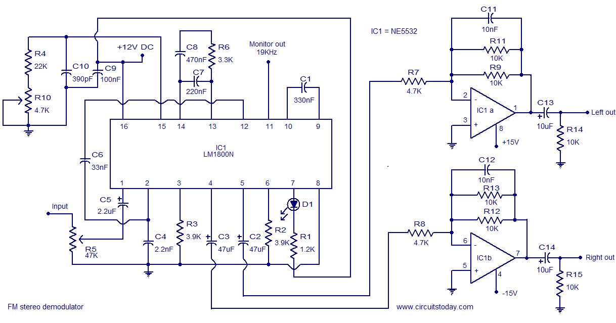
The LM1800 is an integrated FM stereo demodulator IC that incorporates several beneficial features, enabling the design of a high-quality FM stereo demodulator system with excellent sound quality. The LM1800 utilizes phase-locked loop technology to regenerate the 38 kHz...
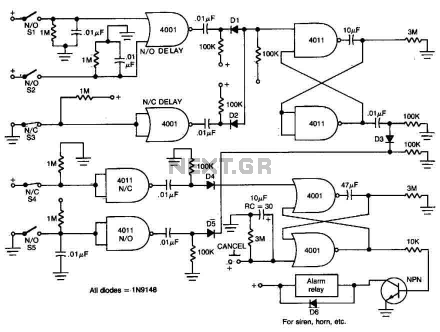
This circuit features open and closed loop contacts (switches 1, 2, 3) that activate the alarm, which remains on for a duration of 5 to 10 minutes. The triggering delay for entrance and exit is set to 27 seconds....
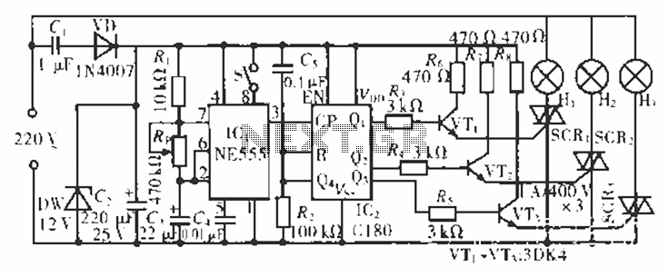
The circuit operates at 220 V AC using a C1 buck converter and a DW regulator. The VD ensures the entire stream is processed, and C2 provides a filtered output of 12 V DC for the voltage supply control...
Warning: include(partials/cookie-banner.php): Failed to open stream: Permission denied in /var/www/html/nextgr/view-circuit.php on line 713
Warning: include(): Failed opening 'partials/cookie-banner.php' for inclusion (include_path='.:/usr/share/php') in /var/www/html/nextgr/view-circuit.php on line 713