
locked out at 2am

The cleaned version presents a narrative that describes a significant moment leading to the development of an idea. This scenario illustrates a common issue encountered in everyday transactions, particularly in cash payments where the availability of smaller denominations can be problematic.
In the context of electronic design, this situation could inspire the development of a payment processing system that facilitates transactions without the need for physical cash. Such a system could involve the integration of various electronic components, including microcontrollers, NFC (Near Field Communication) modules, and secure payment gateways.
A potential schematic for this electronic payment system would include a microcontroller at the core, responsible for processing user inputs and managing communication with payment terminals. The microcontroller could be an ARM Cortex-based chip or an Arduino-compatible board, chosen for its versatility and ease of programming.
The schematic would also feature an NFC module, which allows for contactless payments. This module would be connected to the microcontroller via SPI (Serial Peripheral Interface) or I2C (Inter-Integrated Circuit) protocols, enabling seamless data transfer. Additionally, a secure payment gateway would be integrated into the system, ensuring that all transactions are encrypted and secure.
Power management components, such as voltage regulators and capacitors, would be included to ensure stable operation of the entire system. Input elements like a keypad or touchscreen could be added for user interaction, allowing users to enter payment amounts or select options.
In summary, the described electronic payment system would address the challenges faced in cash transactions by providing a reliable, secure, and user-friendly alternative, inspired by a real-world experience of difficulty in making change.How it all started It all started after a night out back in March 2009. I`d been out for a few post-work drinks and got a taxi home. When I tried to pay the driver, he asked if I had anything smaller than the awkward 50 euro note I was offering. I remembered that I.. 🔗 External reference
Related Circuits
This design was developed by request of a correspondent having made a sort of LED candle and needing to switch off the LED with a puff. This simple, easy to build gadget can be useful as a prop for...
Here is a link to the ExpressPCB layout for this compressor. If you are not familiar with ExpressPCB, look it up. They provide a layout tool that is very easy to use, and you can have boards manufactured for...
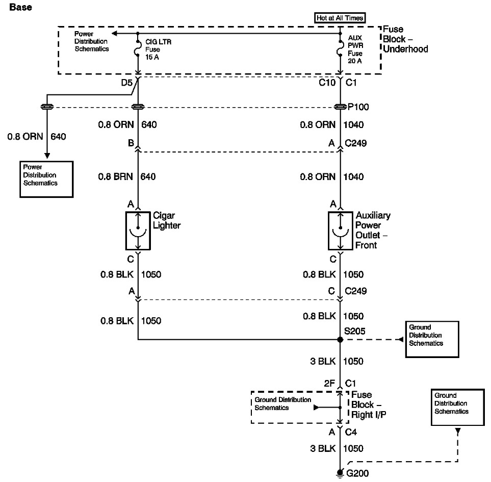
The provided information includes a fuse block diagram with the Auxiliary Power (Aux Pwr) fuse highlighted. It is advisable to check both sides of the fuse using a test light or multimeter to ensure functionality. It is assumed that...
In certain versions of the circuit, the input buffer may be completely absent, while in other versions, the buffer transistors exhibit different biasing configurations or utilize different transistors altogether. Some designs contain significant errors, including biasing issues and incorrect...
This simple adapter circuit is designed specifically for use with the USB Audio DAC featured on this website. With a straightforward modification, it is possible to configure the output of the digital-to-analog converter (DAC) to be pseudo-symmetric, allowing it...
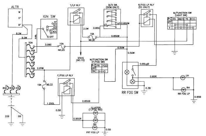
The schematic for the front and rear fog lamps of the Daewoo Korando is illustrated in the accompanying figure. It details the connections and wiring between various components of the fog lamp system, including the alternator, ignition switch, taillamp...