
Daewoo Korando Front and Rear Fog Lamp Schematic and Routing Diagrams

The fog lamp system in the Daewoo Korando is designed to enhance visibility during adverse weather conditions. The schematic displays a comprehensive layout of the electrical connections required for the operation of both front and rear fog lamps.
The alternator serves as the primary power source, supplying voltage to the entire lighting system. The ignition switch is crucial for activating the fog lamps, ensuring that they only operate when the vehicle is in an "on" state. The taillamp relay is included in the circuit to manage the power distribution to the taillights, which may be integrated with the fog lamp system for enhanced visibility.
The b/0 switch functions as a safety mechanism, preventing the fog lamps from being activated when not required. The rear fog lamp relay is responsible for controlling the rear fog lights, allowing them to be turned on or off independently from the front fog lamps. The multifunction switch is an essential component that enables the driver to control various lighting functions, including the fog lamps, from a single interface.
The front fog lamp relay is dedicated to the operation of the front fog lights, ensuring they receive the correct voltage and current for optimal performance. The rear fog switch allows the driver to activate the rear fog lamps, providing additional safety during low visibility conditions. The cluster may include indicators that inform the driver when the fog lamps are active, contributing to an overall safer driving experience.
This schematic is an essential reference for technicians and engineers involved in the maintenance and troubleshooting of the fog lamp system in the Daewoo Korando, ensuring that all components work together effectively to provide enhanced visibility and safety on the road.Front and rear fog lamp schematic of Daewoo Korando shown in the following figure. It shows the connection and wiring between each parts and component of front and rear fog lamp system of the vehicle such as alternator, ignition switch, taillamp relay, b/0 switch, rear fog lamp relay, multifunction switch, front fog lamp relay, rear fog switch, cl uster, and many others. Herein is the schematic : 🔗 External reference
Related Circuits
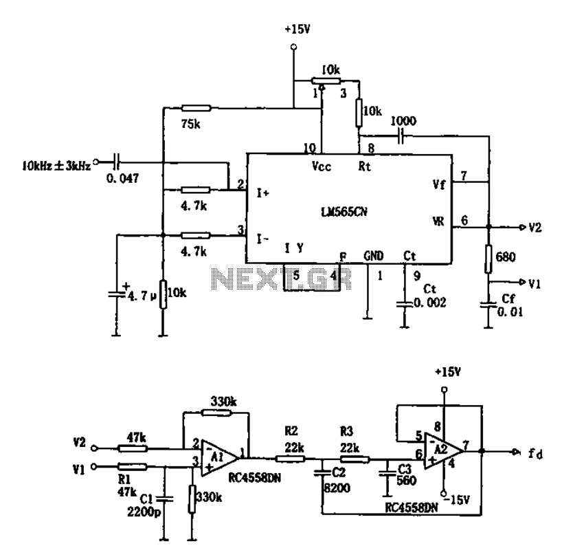
The circuit utilizes a 10 kHz and 3 kHz LM565CN to create an FM demodulation setup. The output diagram (b) illustrates the differential demodulation outputs V1 and V2 from the differential amplifier A1, which provides level displacement and amplification....
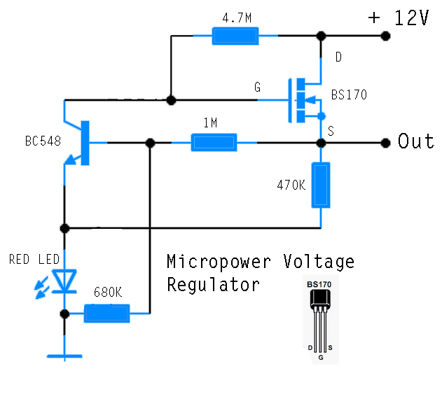
This circuit is designed to power an AVR microcontroller from a 12V lead-acid battery. The watchdog component consumes only 14 µA. While integrated circuits (ICs) from manufacturers like Linear Technology or Maxim can be utilized for this purpose, they...
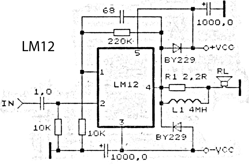
This is an amplifier circuit utilizing the LM12 integrated circuit as the primary amplifier. The amplifier delivers a power output of 150 watts and operates with a load impedance of 4 ohms. It is classified as a high-output power...
The State Jal Boards supply water for a limited duration each day. The timing of the water supply is determined by management, leaving the public unaware of the schedule. In this context, a water alarm circuit can alleviate long...

A very simple dimmer circuit with only the essentials. In this circuit, the values are given for a BT138 at 220V AC. For 115V AC, experimentation with values may be necessary. R1 can vary from one triac to another;...
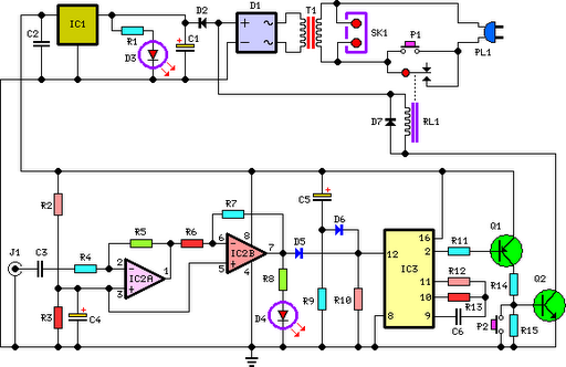
This circuit deactivates an amplifier or any connected device when a low-level audio signal at its input is absent for at least 15 minutes. Pressing P1 turns the device on, supplying power to any appliance connected to SK1. The...