
Logarithmic light-meter circuit
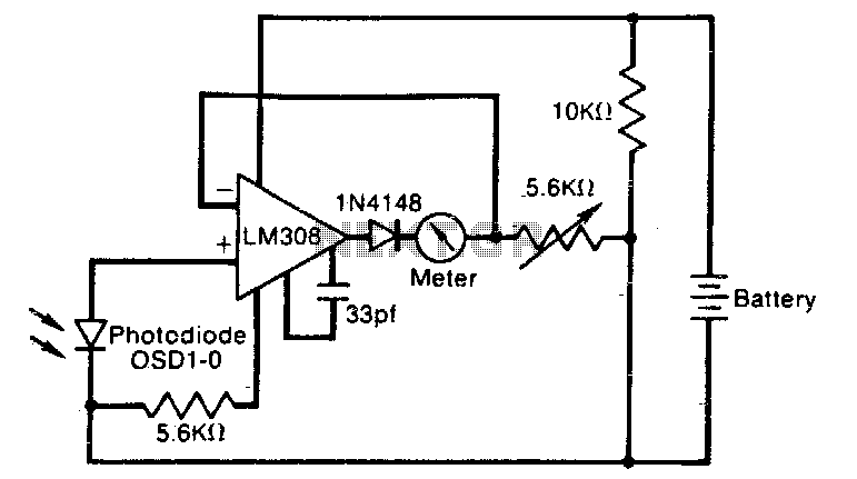
The described circuit utilizes a logarithmic amplifier configuration to measure light intensity. The core principle relies on the logarithmic relationship between the input light power and the output voltage, which is facilitated by the characteristics of a p-n junction diode. This diode exhibits a nonlinear response to varying current, providing the necessary logarithmic scaling of the input signal.
In this configuration, the output of the amplifier is connected to a diode that ensures the output remains at or above zero volts. This is crucial in preventing the meter from saturating or "pegging" when the light levels are low, which could lead to misleading readings due to amplifier bias currents. The bias currents can cause the output to dip below zero, resulting in inaccurate meter deflections.
Resistor R1 plays a pivotal role in calibrating the meter. By adjusting the resistance value, the full-scale deflection of the meter can be modified, allowing for precise calibration according to the specific requirements of the application. This adjustment ensures that the meter accurately reflects the logarithmic relationship between the input light power and the meter reading, providing reliable and consistent measurements across a range of light intensities.
Overall, this circuit is an effective solution for applications requiring accurate light intensity measurements, leveraging the unique properties of diodes and amplifiers to achieve a logarithmic response.The meter reading is directlyjproportiona! to the logarithm of the input light power. The logarithmic circuit behavior arises from the nonlineardiode pnjunction current/voltage relationship The diode in the amplifier output prevents output voltage from becoming negative (thereby pegging the meter), which may happen at low lightlevels due to amplifier bias currents. Rl adjusts the meter full-scale deflection, enabling the meter to be calibrated. 🔗 External reference
Related Circuits
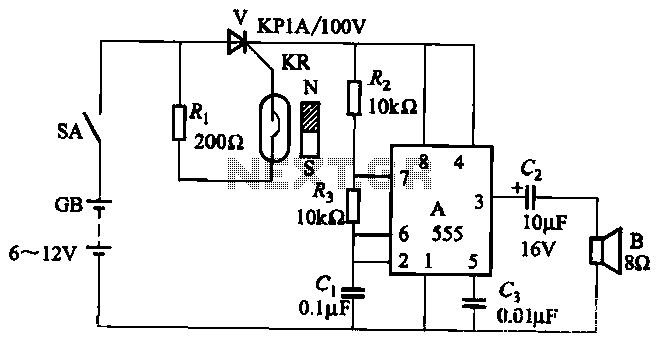
The circuit utilizes a reed switch KR with a control thyristor V for conduction, along with a 555 integrated circuit configured as a multivibrator to function as an alarm generator. When the door is closed, a permanent magnet is...
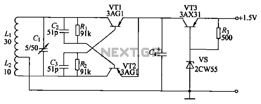
Children often go missing, causing immense suffering and economic losses for families. This situation also presents opportunities for unscrupulous child traffickers to exploit. To address this issue, a radio alarm system has been designed, which consists of a transmitter...
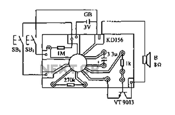
The analog sound KD156 produces a lingering "Ding Dong" sound reminiscent of birds singing, utilizing an integrated circuit. The KD156 is an analog sound generator designed to replicate natural soundscapes, particularly the soothing and familiar tones of birds singing. The...
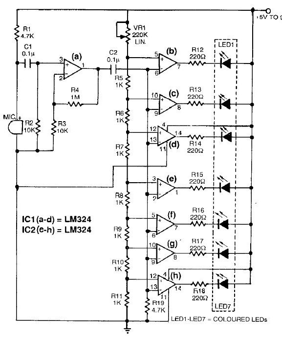
This sound level meter circuit can be used to control the intensity of a sound recording or in a disco. It has 5 measurement domains between 70 and 120 dB. The sound level meter circuit is designed to measure sound...
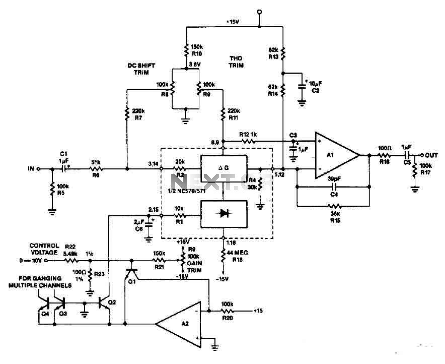
An operational amplifier along with transistors Q1 and Q2 forms an exponential converter to produce an exponential gain control current, which is fed into the rectifier. A reference current of 150 pA, with a voltage of 15 V and...
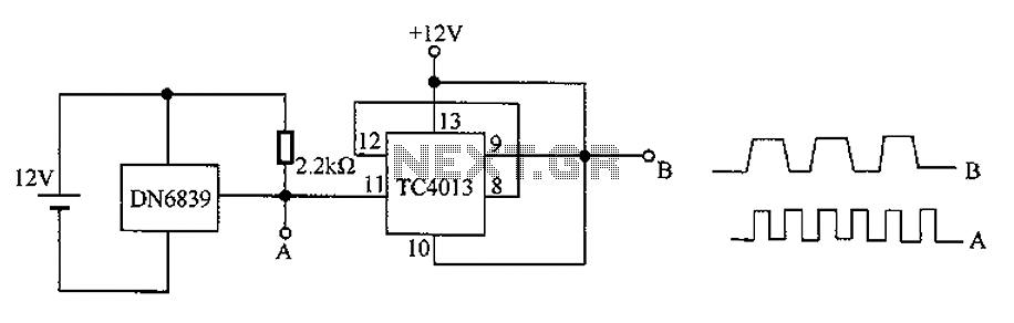
The circuit utilizes the integrated Hall element DN6839 for frequency division. It detects a magnetic field through the pulsating DN6839, generating a pulse waveform. The circuit is designed for applications involving very high-frequency pulsating magnetic fields. It employs the...