
Sound Level Meter Circuit

The sound level meter circuit is designed to measure sound intensity levels in various environments, such as recording studios or entertainment venues like discos. The circuit operates within a range of 70 dB to 120 dB, providing five distinct measurement domains that allow users to monitor sound levels effectively.
The core components of the circuit typically include a microphone sensor that converts sound waves into an electrical signal, an amplifier to enhance the signal strength, and an analog-to-digital converter (ADC) that translates the analog signal into a digital format for processing. Additionally, a microcontroller or a dedicated sound level meter IC may be employed to interpret the digital signal and display the sound level on an LED or LCD screen.
To enhance functionality, the circuit may also incorporate features such as peak hold, which captures the maximum sound level for a brief period, and an adjustable threshold that can be set to trigger alarms or notifications when sound levels exceed a predefined limit. Power supply considerations are crucial; the circuit can be powered by batteries or an external power source, ensuring portability and ease of use.
Overall, the sound level meter circuit serves as a vital tool for monitoring and controlling sound intensity, ensuring optimal audio experiences in various settings.This sound level meter circuit can be used to control the intensity of a sound recording or in a disco. It has 5 measurement domains between 70 and 120 dB;.. 🔗 External reference
Related Circuits
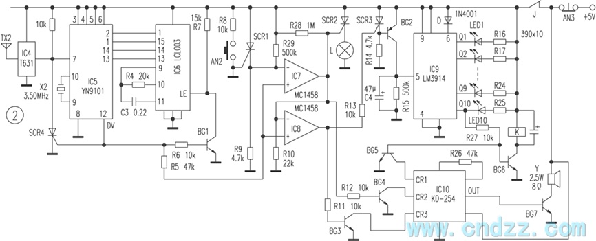
The wireless calling device consists of a calling unit and a host. These two components communicate using a DTMF encoder pulse. Each calling unit is assigned a unique code, although the circuits are identical. The calling unit is depicted...
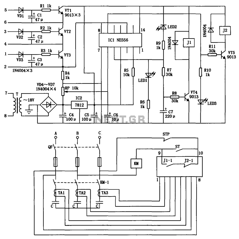
The circuit depicted is utilized in a power supply system to promptly disconnect the power supply in the event of an over-voltage condition during either the grid's on or off phase, thereby protecting the power capacitors. This circuit serves a...
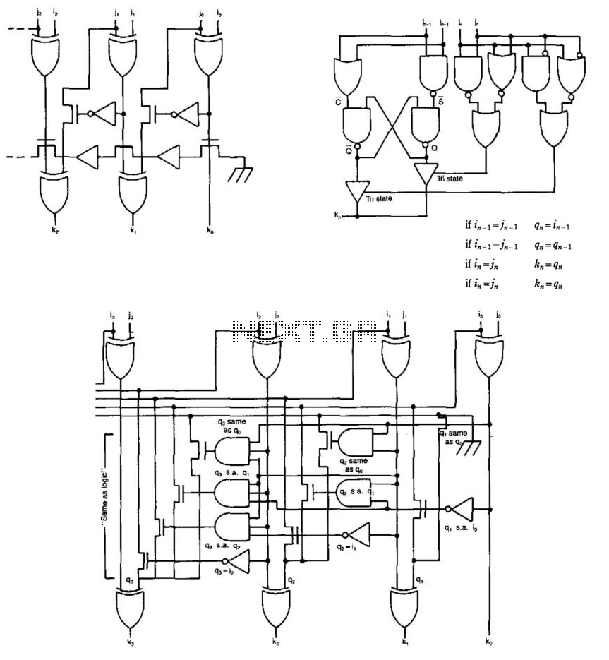
Some circuits that add binary numbers experience time delays due to carry propagation. This issue has been partially addressed by the carry look-ahead adder. However, the complexity of this method typically limits its application to no more than 4...
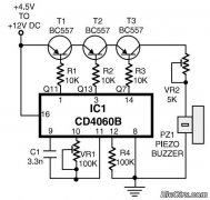
This is a simple home telephone ringtone generator circuit constructed using only a few electronic components. It generates a simulated telephone ringtone and requires a DC supply voltage ranging from 4.5V to 12V. This circuit can be used in...
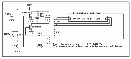
Here is the schematic diagram for a 20 Watt driver. I developed this circuit in 1985, and used it to build a lamp that found much use both as camping light and as emergency light during the then-frequent power...
This article offers a circuit diagram and a discussion on CMOS logic and IC layout for creating a set of attention-getting LED running lights. It details a simple sequential LED flasher or light chaser that can be built, including...