
A child lost alarm circuit

1. The transmitter circuit, illustrated in Figure 13-3a, operates when transistor VT3 conducts, providing a positive bias to transistors VT1 and VT2. This configuration forms a self-excited multivibrator that generates an oscillation frequency between 1600 and 1800 kHz. The frequency selection circuit, comprising inductors L1, L2, and capacitor Ct, allows for adjustment of the transmitted signal's frequency, which is then radiated through a magnetic antenna. The inductors L1 and L2 are constructed with Si-coated wire, having 80 and 40 turns respectively, while the tuning capacitor C1 ranges from 5 to 30 pF.
2. The receiver circuit, depicted in Figure 13-32b, utilizes an antenna L1 to capture the transmitter's signal. The tuning circuit, comprised of L2 and G, selects the remote control signal that matches the transmitter's frequency. The received signal, being very weak, is amplified through a multi-stage amplifier formed by transistors VT1, VT2, and VT3. A four-push sound integrated circuit then generates an audible alert. Due to the low output power, the final stage transistor VT4 enhances the signal to drive a loudspeaker, which emits a sound to alert the guardian to locate the lost child.
This radio alarm system effectively combines simplicity and functionality, providing a reliable solution for ensuring the safety of children and elderly individuals in crowded spaces. The design emphasizes ease of use and rapid response, crucial factors in emergency situations. Children lost a phenomenon often happens, look around, the family should not have brought enormous suffering and economic losses; in addition, also points to unscrupulous child traffickers an opportunity to exploit. For this reason, the design of a radio alarm, children or elderly old man wearing a transmitter, guardianship person with a receiver. When a child or aged man leaving guardian (parent or nanny) Ji from 3-4m, guardian receiving the alarm sound, due to the short distance, it can be found quickly, easily lost.
The device is particularly suitable for the holiday shopping malls, Alhambra and other crowded situations. The device consists of a transmitter and a receiver, whose circuit and principle is as follows: (1) transmitter circuit transmitter circuit shown in Figure 13-3 2a.
When the VT3 conduction, to VT1, VTZ with a positive bias. VT1, VT2 composition self-excited multivibrator start work. Generating a frequency of 1600 ~ 1800kHz frequency oscillation amplitude signal, the Li, L2 and Ct harmonic oscillation frequency selection circuit, c] to adjust the size of the heap transmit signal frequency must be selected in the spring, the magnet antenna out. Wherein Lj, respectively Si-coated wire gauze keys. 80 turns and 40 turns, the tuning capacitor c1 is 5-30pF. The other as shown in FIG. (2) a receiver circuit 13-32b receiver circuit as shown in FIG. Upon receiving antenna Li receiver to the transmitter signal, the L2 and G tuning circuit select remote control signal with the frequency of the transmitter, the received signal is very weak emblem, the VT1, VT2, VT3 multi-stage amplifier, four push sound integrated musical work, due to lower output power, after the last stage VT4 enlarge the loudspeaker Island L work, issued music, remind guardians to find lost children.
Related Circuits

The circuit utilizes a 555 timer along with resistors R4, R5, and capacitor C1 configured in a controllable multivibrator mode. This setup forces the reset terminal (pin 4) to a specific state, allowing for control of the external logic...
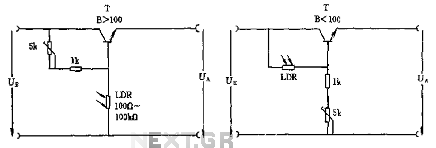
The circuit depicted involves a photoresistor (LDR) connected to a transistor, which operates at either a high or low level based on light conditions. The amplification factor of the transistor is 100, which is adequate for the application. The...

An LED flasher circuit can be constructed using a 555 integrated circuit (IC). The use of the 555 IC allows for greater flexibility in adjusting the flashing rate of the LED. This LED flasher circuit is similar to other...

This circuit needs a Faraday shield, which is connected to 0V. To make this one wrap a tin foil around the coil and connect to 0V. Then you can use this circuit to find metal. Tune your mw radio...

This circuit functions as an oscillator, capable of generating a sound wave or tone. The frequency of the tone, whether high or low, is adjustable via a variable resistor. The volume produced by this circuit is substantial; therefore, it...

C4 and L form a resonator, where the resonant frequency corresponds to the FM transmitting power of the microphone. According to the component parameters in the diagram, the transmission frequency can range from 88 to 108 MHz. The frequency...