
logic overvoltage protection
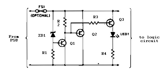
The logic overvoltage protection power supply is designed to safeguard sensitive electronic components from voltage spikes that could potentially damage them. This circuit typically employs a combination of voltage clamping devices, such as Zener diodes or transient voltage suppression (TVS) diodes, to limit the voltage to safe levels.
The primary function of this protection circuit is to monitor the input voltage and activate protective measures when the voltage exceeds a predetermined threshold. The circuit usually consists of a voltage divider to sense the input voltage, an operational amplifier to compare the sensed voltage against a reference level, and a switching element, such as a MOSFET or relay, that disconnects the load when overvoltage conditions are detected.
In a typical schematic, the input voltage is fed into a voltage divider network, which reduces the voltage to a level suitable for the operational amplifier. The operational amplifier is configured as a comparator, with its non-inverting input connected to the output of the voltage divider and its inverting input connected to a stable reference voltage. When the input voltage exceeds the reference voltage, the output of the operational amplifier switches to activate the control element, which interrupts the power supply to the load.
Additional features may include LED indicators to provide visual feedback on the operational status of the circuit, as well as a reset mechanism to restore power once the overvoltage condition has been resolved. Proper component selection is crucial for ensuring the circuit's effectiveness, including choosing diodes with appropriate breakdown voltages and ensuring that the switching element can handle the load current without overheating.
Overall, the logic overvoltage protection power supply circuit is an essential component in electronic designs where voltage regulation and protection are critical for maintaining system integrity and reliability.Logic overvoltage protection power supply. Go to that page to read the explanation about above power supply related circuit diagram. 🔗 External reference
Related Circuits
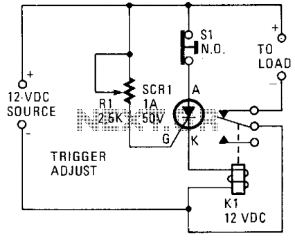
A silicon-controlled rectifier (SCR) is connected in parallel with the 12-V line and linked to a normally-closed 12-V relay, designated as K1. The gate circuit of the SCR is utilized to monitor the applied voltage. While the applied voltage...
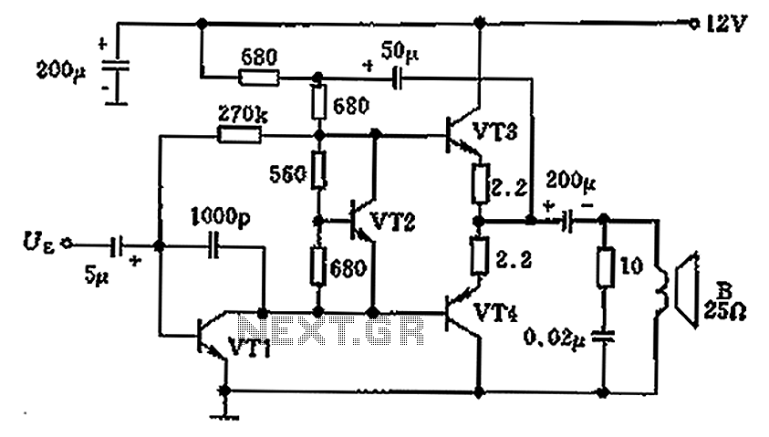
The overload protection circuit operates at a power of 650 mW with a supply voltage of 12 V and is designed for a speaker with an impedance of 25 ohms. The component specifications include: VT1 as transistor NB111EH/J, VT2...
The 5 volt regulated power supply for TTL and 74LS series integrated circuits has to be very precise and tolerant of voltage transients. These ICs are easily damaged by short voltage spikes. A fuse will blow when its current...
A long time ago, when telephones were simple and reliable from an electrical standpoint, telecom operators installed surge protection on all telephone lines exposed to storm risks. Paradoxically, with the advent of delicate and expensive equipment such as electronic...
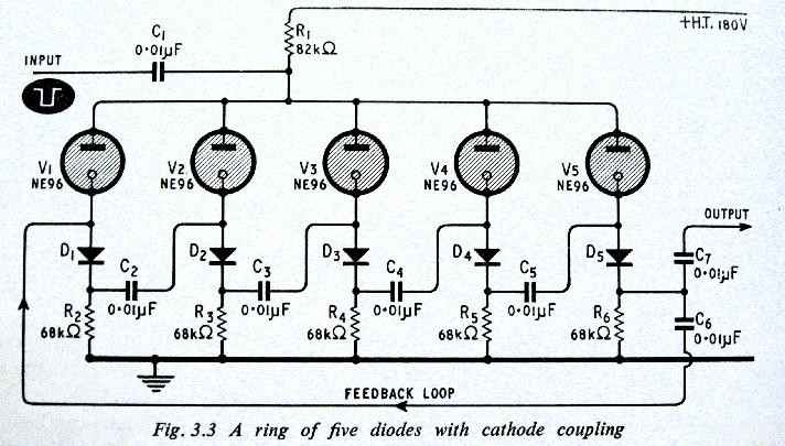
The above shows a home-built digital clock that utilizes Nixie tubes for display. Unlike most contemporary Nixie clocks, this design does not employ transistors or integrated circuits for driving the tubes. Instead, the driving logic is constructed using neon...
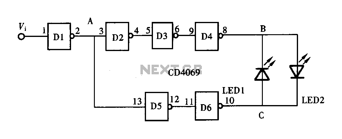
A logic pen, also known as a logic detection probe, is a commonly used tool for detecting the logic state at various points within digital circuits. The logic states in digital circuits are typically categorized into three types: a...