
Over-voltage protection circuit
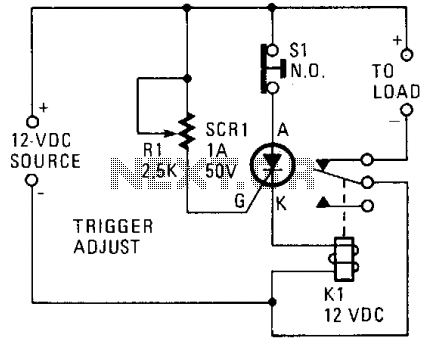
The described circuit employs a silicon-controlled rectifier (SCR) to manage the operation of a relay in response to voltage changes in a 12-V power supply line. The SCR is strategically placed in parallel with the voltage line to monitor the voltage levels effectively. Its gate terminal is connected to a voltage divider or sensing circuit that includes a resistor, R1, which sets the trigger point for the SCR. This configuration ensures that the SCR remains in an off state while the voltage stays below 12 V, thereby maintaining the closed state of relay K1 and enabling current to flow to the connected load.
When the voltage exceeds the predetermined threshold of 12 V, the current flowing through R1 becomes sufficiently high to trigger the SCR. This transition causes the SCR to enter a conductive state, effectively short-circuiting the relay coil and opening the contacts of K1. Consequently, the load is disconnected from the power supply, preventing potential overvoltage conditions that could damage the load.
The choice of R1 is critical as it determines the sensitivity of the SCR to voltage changes. Adjusting R1 allows for fine-tuning the voltage level at which the SCR will trigger, providing flexibility in the circuit's operational parameters. This design is particularly useful in applications where overvoltage protection is needed, ensuring that sensitive devices are safeguarded against voltage spikes.
In summary, this circuit exemplifies a simple yet effective method for controlling power delivery to a load based on voltage levels, using a silicon-controlled rectifier in conjunction with a relay to provide reliable operation and protection.A silicon-controlled rectifier is installed in parallel with the 12-V line and connected to a normally-closed 12-V relay, K1. The SCR's gate circuit is used to sample the applied voltage. As long as the applied voltage stays below a given value, SCR1 remains off and Kl's contacts remain closed, thereby supplying power to the load.
When the source voltage rises above 12 V, sufficient current is applied to the gate of SCR1 to trigger it into conduction. The trigger point of SCR1 is dependent on the setting of R1. Once SCR1 is triggered (activating the relay), K1's contacts open, halting current flow to the load. 🔗 External reference
Related Circuits
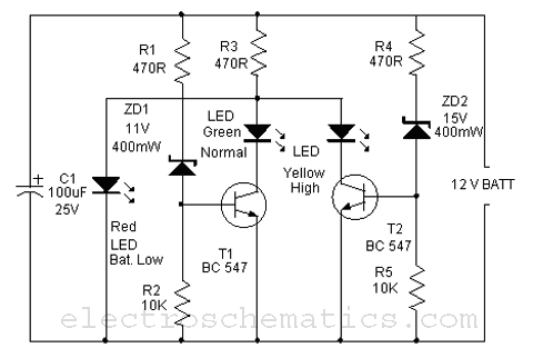
This is a simple battery monitor circuit designed for a quick assessment of a 12-volt lead-acid battery. Continuous monitoring of battery charge is essential to extend its lifespan. The battery monitor circuit typically consists of a voltage divider, an operational...
The DTMF infrared remote control circuit utilizes a DTMF encoded signal that can be decoded by a specialized decoder and the PLL audio decoder LM567. However, a DTMF encoded signal decoded by a single decoder yields only one frequency....
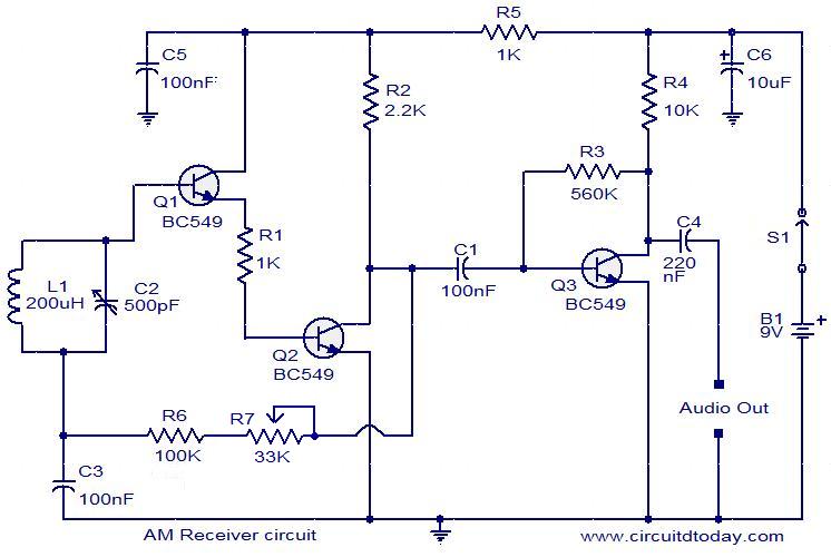
Circuit diagram of a modulator circuit in a transmitter and receiver of amplitude modulation. The modulator circuit in an amplitude modulation (AM) transmitter and receiver plays a crucial role in the process of encoding information onto a carrier wave. In...
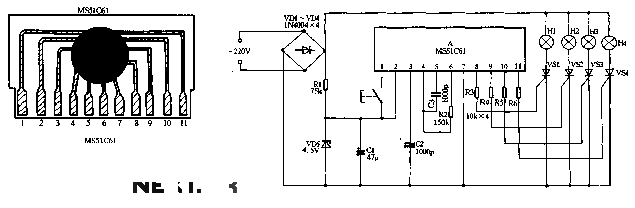
The circuit utilizes a 220V AC input, which is converted to DC using a VD1-VD4 bridge rectifier. This rectified voltage is used to power four lights (H1 to H4). The circuit also includes a resistor (R1) for voltage limiting...
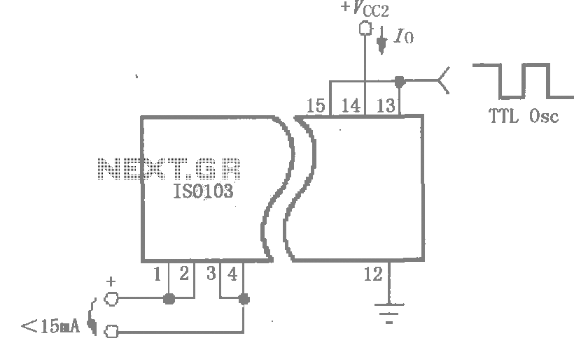
This circuit is designed to reduce power consumption in an ISO103 application. It operates with a Vcc1 current of less than 15mA for multi-channel synchronous applications. An oscillator, as illustrated in the figure, can be utilized to generate a...

The schematic for this tutorial is straightforward. It involves connecting the ADXL320 sensor to the PIC microcontroller and an LED. The power supply is assumed to be a +5V battery to power the PIC. A custom power circuit can...