
Logic PSU with Overvoltage Protection
The circuit described is a precision 5V regulated power supply specifically designed for powering TTL (Transistor-Transistor Logic) and 74LS (Low Power Schottky) series integrated circuits. The critical aspect of this design is its ability to maintain a stable output voltage while being highly responsive to transient voltage spikes, which can occur due to various factors such as load changes or inductive kickbacks.
The power supply typically utilizes a linear voltage regulator, which can provide a clean and stable output voltage. However, to enhance transient response and protect sensitive ICs, a zener diode is employed in the feedback path of the regulation circuit. This zener diode acts as a voltage reference and will clamp the output voltage if it exceeds a predetermined threshold, thus preventing damage to the connected ICs.
Incorporating a fast-acting electronic fuse or a resettable fuse (polyfuse) in the circuit design is essential. Unlike traditional fuses that may take several hundred milliseconds to react to overcurrent conditions, the electronic fuse can detect excessive current in microseconds. This rapid response is crucial for protecting sensitive components from damage caused by voltage spikes.
The circuit may also include additional components such as capacitors for filtering and stabilization, ensuring that the output voltage remains steady during transient conditions. Input capacitors help to smooth out any fluctuations from the power source, while output capacitors can provide additional charge during sudden changes in load.
The overall design emphasizes reliability and protection, making it suitable for applications where TTL and 74LS series ICs are used, such as in digital logic circuits, microcontroller interfacing, and other electronic systems where voltage stability is paramount. Proper PCB layout practices should be followed to minimize inductance and resistance in the power traces, further enhancing the performance of the power supply circuit.The 5 volt regulated power supply for TTL and 74LS series integrated circuits, has to be very precise and tolerant of voltage transients. These IC`s are easily damaged by short voltage spikes. A fuse will blow when its current rating is exceeded, but requires several hundred milliseconds to respond.
This circuit will react in a few microseconds, triggered when the output voltage exceeds the limit of the zener diode. 🔗 External reference
Related Circuits
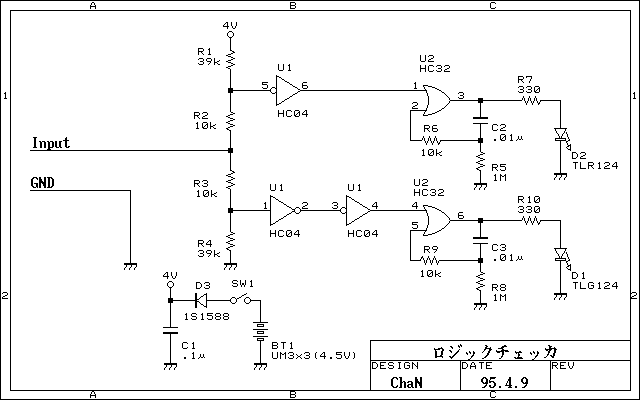
Simplified logic checker. Logic voltage levels have the ability to display LED. "H" in the LED is green, "L" and red LED lights, and so both the open and goes out. But not only that was put on the...
A two-transistor Darlington connection offers a very high input impedance, ensuring that it does not load the logic circuit being monitored. This configuration drives an LED that illuminates when a logic high (1) is present at the input. The two-transistor...
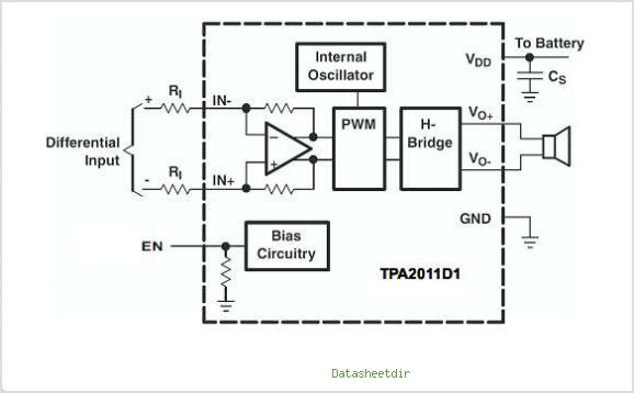
The TPA3007D1 is a 6.5-W mono bridge-tied load (BTL) class-D audio power amplifier featuring high efficiency, which eliminates the need for heat sinks. This amplifier can drive 8-ohm speakers with only a ferrite bead filter required to reduce electromagnetic...

Figure 4-27 (b) line demonstrates a configuration that enhances the output current waveform DC voltage compared to the line in Figure 4-27 (a). This configuration can be utilized for motors with larger capacities. The circuit illustrated in Figure 4-27 (b)...
A variable power supply with adjustable voltage and current outputs utilizes the L200 regulator. This power supply features independent voltage and current limits. The mains transformer is rated at 12 volts with a 2 amp secondary output, while the...
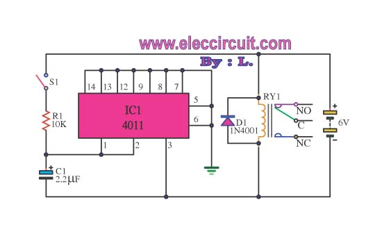
This circuit illustrates the use of the 4011 integrated circuit (IC) for a surge protection electronic circuit diagram. Features include the ability to delay the activation of other appliances connected to the output. The 4011 IC is a quad 2-input...