
logic tutor circuit

The circuit diagram for a logic tutor kit serves as a foundational tool for understanding digital logic principles. This diagram typically includes various logic gates such as AND, OR, NOT, NAND, NOR, XOR, and XNOR, which are essential for building complex digital circuits. Each component should be clearly labeled with its corresponding value and type to facilitate easy identification during assembly.
In creating the diagram, it is crucial to maintain clarity and organization. Conductors should be drawn with straight lines, intersecting at right angles to minimize confusion and enhance readability. Junctions where conductors meet must be marked with black circles to indicate connectivity, ensuring that anyone reviewing the diagram can easily follow the circuit pathways.
Furthermore, the use of a ruler will enhance the neatness of the diagram, allowing for a professional appearance that reflects the quality of the design. Each component’s symbol should adhere to standard conventions to promote universal understanding among engineers.
In addition to the visual aspects, the schematic should include a legend or key that explains the symbols used, further aiding comprehension. This is particularly important for novice engineers or students who may be unfamiliar with specific logic gate symbols.
Ultimately, the goal of the circuit diagram is not only to provide a blueprint for construction but also to serve as an educational tool. A well-crafted diagram will assist learners in grasping the concepts of digital logic, enabling them to explore and innovate in the field of electronics.This circuit diagram for a logic tutor kit was made from MS Word graphics. Although it's usual to use software nowadays, you may need to do it the old-fashioned, low-tech, way. Use a sharp pencil; Use a ruler; Conductors meet at right-angles; Junctions have black circles; Put down the values of the components.
A bad circuit diagram is use to neither man nor beast. A good circuit diagram is one that another electronic engineer can pick up and build the circuit that you have designed. And it will work in exactly the same way as your original circuit. 🔗 External reference
Related Circuits
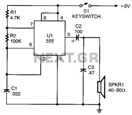
A 555 timer configured as an astable multivibrator is used in this circuit to generate an audio note. The capacitance value can be changed to vary the audio note as desired. The circuit utilizes a 555 timer IC, which...

Filter regulators, solenoid valves, quick exhaust valves, flowline pilots - Welcome to Bifold Fluidpower Ltd. Bifold Fluidpower Ltd. specializes in a range of fluid power components that include filter regulators, solenoid valves, quick exhaust valves, and flowline pilots. Each of...
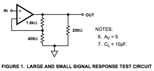
Here is a circuit diagram for a signal response test circuit from the specification sheet for a HA-5195 operational amplifier. It appears to be a non-inverting amplifier circuit with a gain of 5, along with a 200-ohm resistor connecting...
In its simplest form, a voice-over unit is just a microphone and change-over switch feeding an amplifier, the output from the microphone having priority over the amplifiers audio signal when the "push-to-talk" switch is pressed. In this circuit, a...

This circuit is a 92%-efficient power supply for cold-cathode fluorescent lamps (CCFLs), which are used to backlight LCDs in portable equipment. The efficiency depends heavily on the component types, particularly C1, Q1, Q2, L1, and T1, whose manufacturers are...
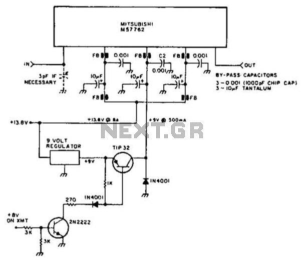
Using a Mitsubishi M57762 amplifier module, this amplifier delivers 20 W output at 1296 MHz. A single 12 V nominal power supply can be used. The Mitsubishi M57762 is a high-performance RF amplifier designed for applications requiring significant power output...
Warning: include(partials/cookie-banner.php): Failed to open stream: Permission denied in /var/www/html/nextgr/view-circuit.php on line 713
Warning: include(): Failed opening 'partials/cookie-banner.php' for inclusion (include_path='.:/usr/share/php') in /var/www/html/nextgr/view-circuit.php on line 713