
op amp Why the resistor in this op-amp circuit

The described circuit utilizes the HA-5195 operational amplifier, which is designed for high-speed applications and can operate with a dual power supply. The non-inverting amplifier configuration allows for a straightforward gain setup, where the gain (Av) can be calculated using the formula Av = 1 + (R2/R1). In this case, the resistor values should be selected to achieve the desired gain of 5, which implies that R2 is five times the value of R1.
The inclusion of a 200-ohm resistor between the output (Vout) and ground serves to stabilize the output signal and dampen potential oscillations, which can be particularly useful in high-frequency applications where stability is critical. This resistor may also help in providing a defined output impedance, which is beneficial when interfacing with other circuit stages or loads.
In the circuit, the power supply connections to the HA-5195 should be made in accordance with the manufacturer's recommendations, ensuring that the supply voltage is appropriate for the operational amplifier's specifications. Proper bypass capacitors should also be included near the power supply pins to filter out noise and ensure stable operation.
Overall, this circuit is suitable for testing the signal response characteristics of the HA-5195 op amp, allowing for evaluation of its performance in real-world scenarios. The configuration can be expanded or modified by altering resistor values or adding additional components, such as capacitors for frequency response shaping, depending on the specific testing requirements.Here`s a circuit diagram for a signal response test circuit from the spec sheet for a HA-5195 op amp and looks like a non-inverting amplifier circuit with a gain of 5, plus the 200 © resistor between Vout and ground: 🔗 External reference
Related Circuits
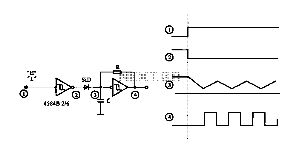
The circuit generates a controlled pulse signal. When a high pulse signal is applied to the input terminal O (start), the output pulse signal is activated. Conversely, when a low signal is received at the input terminal O (stop),...
The following circuit illustrates a Repeating Interval Timer Circuit Diagram. This circuit is based on the CMOS 4060 integrated circuit (IC). Features include a 6-pin output. The Repeating Interval Timer Circuit utilizing the CMOS 4060 IC is designed to generate...
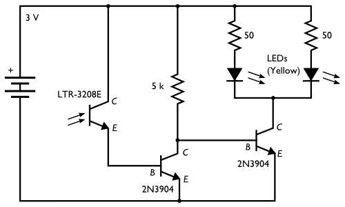
Here is an inexpensive electronic circuit that can be built to place in a Jack-o'-lantern. It provides power to drive a few LEDs at night and automatically turns them off during the daytime. This is a simple and automatic...
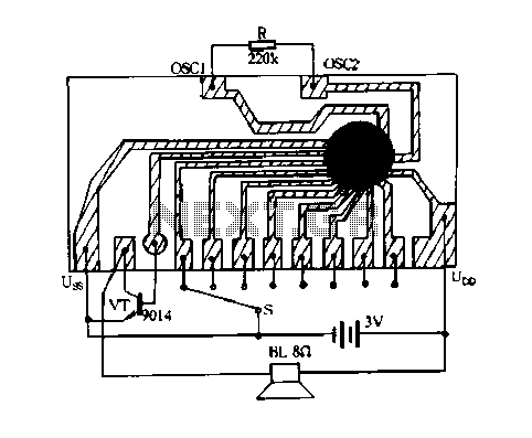
Constantly changing light and sound analog controller circuit 05 The circuit described is an analog controller designed to modulate light and sound in a dynamic manner. This type of circuit typically employs a combination of resistors, capacitors, and operational amplifiers...
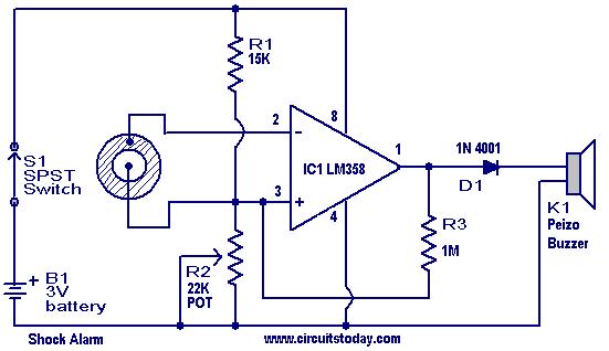
This is a simple shock-sensitive alarm circuit with numerous applications, ranging from home use to automobiles. The primary application of this circuit is as an anti-theft alarm for vehicles. A piezoelectric sensor is employed as the shock sensor and...
This circuit functions as a camera switch, allowing multiple cameras to be connected to a single monitor. It can operate in both manual and automatic modes. In automatic mode, the circuit utilizes a 555 astable multivibrator to generate a...