
Long Delay Timer Circuit
The timer circuit is a practical solution for users who wish to enjoy audio entertainment without the worry of draining the battery. The circuit operates based on a simple RC (resistor-capacitor) timing mechanism, where R1 controls the charge time of capacitor C1. The choice of values for R1 and C1 is crucial, as they determine the overall time delay before the circuit switches off. A longer resistance or capacitance will yield a longer delay, allowing for customization based on user preference.
IC1, typically a CMOS logic gate IC, is used for its low power consumption and high input impedance, which is suitable for battery-operated devices. The parallel configuration of the gates ensures that the signal is amplified, allowing for reliable operation even with minimal voltage levels from C1. Transistor Q1 serves as a switch that can handle a moderate load, making it ideal for directly powering small devices like portable radios. For applications requiring more power, the relay adds versatility by enabling control of higher voltage devices while isolating the timer circuit from the load.
The activation mechanism through switch P2 is simple yet effective. The momentary closure of P2 initiates the discharge of C1, triggering the timer sequence. The gradual charging of C1, governed by R1, ensures that the timer operates smoothly without abrupt cut-offs. The addition of P1 allows users to manually stop the timer, providing an extra layer of control over the operation.
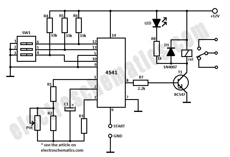
Overall, this timer circuit is an efficient and user-friendly solution for automatically powering down devices, enhancing battery life while providing convenience for users engaged in leisure activities.This timer was designed mainly to switch off a portable radio after some time: in this way, one can fall asleep on the sand or on a hammock, resting assured that the receiver will switch off automatically after some time, saving battery costs. R1 and C1 provide a very long time constant. When P2 is momentarily closed, C1 discharges and the near ze ro voltage at its positive lead is applied to the high impedance inputs of the four gates of IC1 wired in parallel. The four paralleled gate outputs of the IC go therefore to the high state and the battery voltage is available at Q1 Emitter.
When P2 is released, C1 starts charging slowly through R1 and when the voltage at its positive lead has reached about half the battery voltage, the IC gate outputs fall to zero, stopping Q1. This transistor can directly drive a portable radio receiver or different devices drawing a current up to about 250mA.
Connecting a Relay across the Emitter of Q1 and negative ground, devices requiring much higher voltage and current operation can be driven through its contacts. Pushing on P2 for 1 to 5 seconds, the circuit starts and then will switch off after about 35 minutes.
This time delay can be varied by changing R1 and/or C1 values. P1 will stop the timer if required. 🔗 External reference
Related Circuits
The circuit described is a simple intercom system that utilizes a single LM386 integrated circuit, a 2N3904 transistor, and several additional components. The LM386 is a widely recognized amplifier IC commonly employed by electronics enthusiasts in audio applications. In...
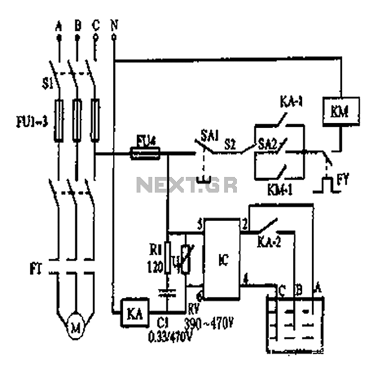
An automatic water tank system is illustrated in the circuit diagram. The circuit employs a PSSR AC solid-state relay, which is a new type of solid-state relay designed for AC applications. Unlike traditional solid-state relays (SSR), this PSSR not...
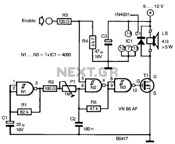
A CD4093 chip and several components form a siren oscillator that drives power MOSFET Tl. A speaker is directly powered by this device. The siren is activated by a logic high signal applied to the ENABLE input. The circuit comprises...
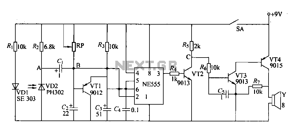
The circuit is designed to detect clogging in a wheat planter by utilizing light-emitting diodes (LEDs) and photodiodes. When the light path is obstructed by particles, the photodiode receives less light, causing the resistance of VD2 to increase. This...
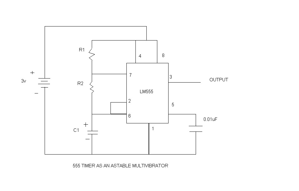
An astable multivibrator, commonly referred to as a free-running multivibrator, is a circuit that generates rectangular waves without the need for external triggering. The timing characteristics of this circuit are determined by the values of the resistors and capacitors...
To initiate the timing process, there are two options available: either connect the START point to ground (GND), in which case the timer activates when connected to the voltage supply, or employ a switch to start the timer. The timing...