
A 555 TIMER LED FLASHER CIRCUIT

The astable multivibrator is a versatile circuit widely used in applications requiring clock pulses or timing signals. This circuit operates continuously, producing a square wave output that alternates between high and low states. The frequency of oscillation and the duty cycle are primarily influenced by the selection of resistors R1 and R2, as well as the capacitor C1.
In this configuration, when the circuit is powered, the capacitor C1 charges and discharges through the resistors R1 and R2, creating a cycle of oscillation. The output at Pin 3 can be used to drive other digital circuits or components, providing a stable timing signal. The bypass capacitor at Pin 5 serves to filter out any noise from the power supply, ensuring stable operation of the multivibrator.
The values of R1, R2, and C1 can be calculated to achieve the desired frequency (f) of oscillation using the formula:
f = 1.44 / ((R1 + 2*R2) * C1)
This design allows for flexibility in frequency adjustment by varying the resistor and capacitor values. The astable multivibrator is an essential building block in digital electronics, commonly utilized in applications such as timer circuits, pulse width modulation, and frequency generation.An astable multivibrator, often called a free running multivibrator, is a rectangular wave generating circuit. The circuit doesnt need any triggering. The timing of the circuit is determined by the resistors and the capacitors used in it. The details of the astable multivibrator are: Pin1 is grounded; Pins 4 and 8 are shorted, Pin 3 gives the timi
ng output; Pins2 and 6 are short circuited and connected with a capacitor C1; at Pin 5 a bypass capacitor is used having value of 0. 01uF; a supply of 3v is given to the circuit, the suppy can be more upto 9v. Pin 7 is connected through Pin 4 through a resistor R1and also with pin 6 through resistor R2. 🔗 External reference
Related Circuits

This circuit operates with 230V and can be used to decorate parties. It features a DIAC ER 900 and a TRIAC BTW 11-400. The circuit utilizes a DIAC (Diode for Alternating Current) and a TRIAC (Triode for Alternating Current) to...

The egg hatching incubator circuit comprises a power supply circuit, a constant temperature control circuit, and a sound and light alarm circuit, as illustrated in Figure 4-7. The power supply circuit includes a power switch (S1), a fuse (FU2),...
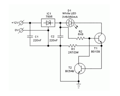
A simple and safe white LED driver circuit has been designed for use in 12V automobiles, allowing for the efficient operation of standard high-efficiency white LED modules powered by automotive battery systems. The circuit utilizes a fixed voltage regulator...
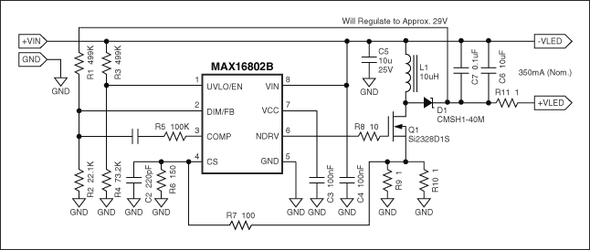
Flyback LED drivers are versatile as they can be utilized in applications with input voltages either above or below the necessary output voltages. They feature a straightforward circuit configuration that maintains a constant LED current without the need for...
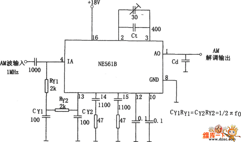
The figure illustrates a bilateral band modem circuit utilizing the NE561B component. The input modulating signal operates at a loading frequency of f0 = 1 MHz. When the AM modulation signal is applied to the input terminal of the...

The saving lamp circuit features two main types: glass cover and exposed. The glass cover variants include three series: spherical, cylindrical, and processing types. The first two series consist of four variations: transparent, carved, engraved, and white. These lamps...